Material cutting and clamping device of upsetting machine and working method

A technology of upsetting forging machine and shearing, applied in forging/pressing/hammer devices, operating devices, manufacturing tools, etc., can solve the problems of poor section quality, complex structure of shearing and clamping devices, etc., and achieve good quality and simple structure , high reliability effect

Active Publication Date: 2013-11-06
杨东佐
View PDF7 Cites 11 Cited by
  • Summary
  • Abstract
  • Description
  • Claims
  • Application Information

AI Technical Summary

Problems solved by technology

[0002] The existing shearing and clamping devices used on upsetting machines are all semicircular shearing structures. For example, in the patent document with application number 201020124750.1, a multi-station die rotary upsetting machine is disclosed, and the shearing clamps are specifically disclosed. The material device includes a material shearing seat, a material shearing rod that is slidably installed in the material shearing seat back and forth through a pressing plate, a material shearing rod driving mechanism that drives the reciprocating movement of the material shearing rod, a shearing knife fixed on the material shearing rod, and a shearing rod. The material knife cooperates with the clamping knife of t...

Method used


Image

  • Material cutting and clamping device of upsetting machine and working method
  • Material cutting and clamping device of upsetting machine and working method
  • Material cutting and clamping device of upsetting machine and working method

Examples


no. 1 approach

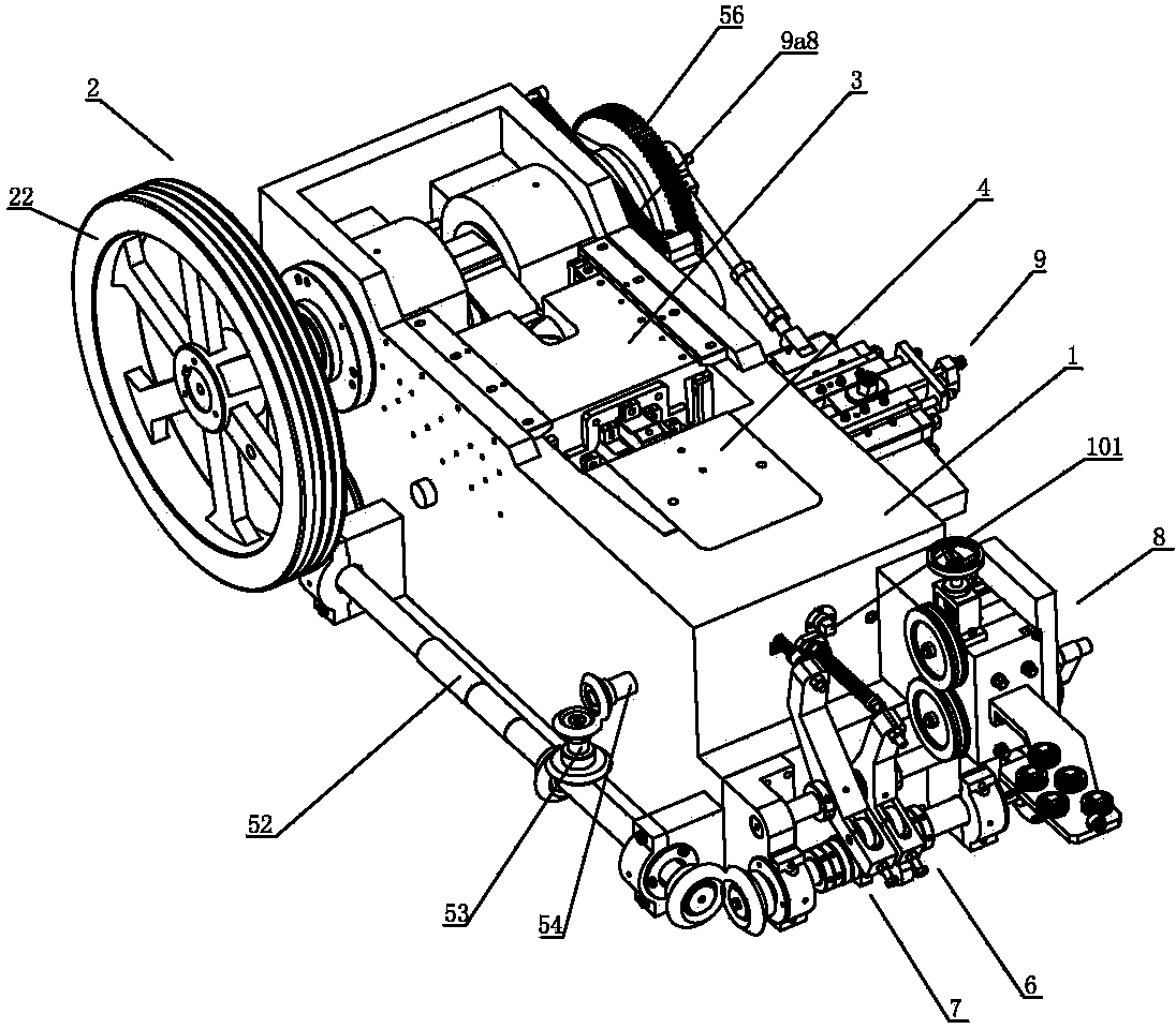
[0034] Such as figure 1 As shown, the upset forging machine includes a frame 1, a die assembly driving mechanism 2, a die assembly 3, a die assembly 4, a die rotating mechanism 5, a feeding mechanism 6, a die positioning device 7, a feeding device 8, a cutting material The clamping device 9 and the pushing device 9a.

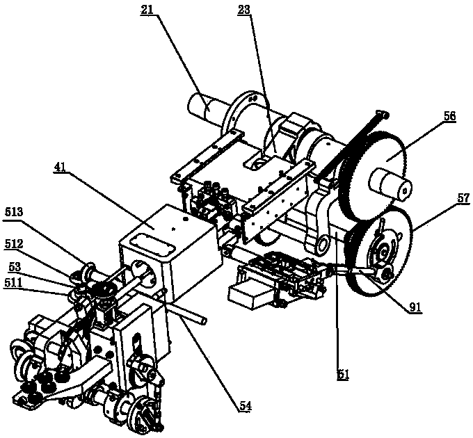
[0035] Such as Figure 1 to Figure 4 As shown, the die assembly driving mechanism 2 includes a crankshaft 21, a pulley 22 and a connecting rod 23, the crankshaft 21 is mounted on the frame 1 through a bearing, the pulley 22 is mounted on the crankshaft 21, and one end of the connecting rod 23 is pivotally connected to the crankshaft 21, the other end is pivotally connected to the large slider 32.

[0036] Such as figure 2 As shown, the die assembly 3 includes a die base 31 , a large slider 32 , a die backing plate 33 and a die 34 . Among them, the die base 31 is installed on the frame 1; the large slider 32 is slidably installed on the die base 31, when the...

no. 2 approach

[0063] Such as Figure 8 As shown, the upsetting machine with adjustable one-way rotating thimble includes frame 1, die assembly drive mechanism 2, die assembly 3, die assembly 4, die rotation mechanism 5, ejector mechanism 6, die positioning device 7 , Feeding device 8, cutting and clamping device 9 and pushing device 9a.

[0064] Such as Figure 8 to Figure 11 As shown, the die assembly driving mechanism 2 includes a crankshaft 21, a pulley and a connecting rod 23, the crankshaft 21 is mounted on the frame 1 through a bearing, the pulley is mounted on the crankshaft 21, and one end of the connecting rod 23 is pivotally connected to the crankshaft 21 , the other end is pivotally connected to the large slider 32.

[0065] Such as Figure 9 As shown, the die assembly 3 includes a die base 31 , a large slider 32 , a die backing plate 33 and a die 34 . Among them, the die base 31 is installed on the frame 1; the large slider 32 is slidably installed on the die base 31, when t...


PUM


Abstract

The invention discloses a material cutting and clamping device of an upsetting machine and a working method. The material cutting and clamping device comprises a material cutting driving device, a material cutting rod and a material cutting block; a material cutting tool is arranged inside the material cutting block; a blank material ejecting rod with one end extends into the material cutting tool is arranged inside the material cutting block. According to the working method of the material cutting and clamping device, when materials are delivered into the material cutting tool, the material cutting driving device drives the material cutting rod to move, the material cutting rod drives the material shearing block to move, the material cutting block drives the material cutting tool to move, the material cutting tool shears off the materials to form into blank materials during moving, the blank materials push the blank material ejecting rod when are delivered into a cavity die for feeding through the material cutting tool, the blank materials are ejected into the cavity die through the blank material ejecting rod, the material cutting rod, the material cutting block and the material cutting tool are reset under the function of a driving block. The material cutting and clamping device has the advantages of enabling the structure to be simplified and improving quality of blank material sections.

Description

technical field [0001] The invention relates to an upsetting machine, in particular to a cutting and clamping device on the upsetting machine. Background technique [0002] The existing shearing and clamping devices used on upsetting machines are all semicircular shearing structures. For example, in the patent document with application number 201020124750.1, a multi-station die rotary upsetting machine is disclosed, and the shearing clamps are specifically disclosed. The material device includes a material shearing seat, a material shearing rod that is slidably installed in the material shearing seat back and forth through a pressing plate, a material shearing rod driving mechanism that drives the reciprocating movement of the material shearing rod, a shearing knife fixed on the material shearing rod, and a shearing rod. The material knife cooperates with the clamping knife of the clamping mechanism for clamping the blank, so that the clamping knife and the shearing knife ar...

Claims


Application Information

Patent Timeline
IPC IPC(8): B21K27/06
Inventor 杨东佐
Owner 杨东佐
Why Eureka
Try Eureka