Pull rod type composite spring three-dimensional shock isolation support

A technology of composite springs and shock-isolation bearings, which is applied in the direction of springs, shock-proof, protective buildings/shelters, etc., can solve the problems of increasing the complexity of the shock-isolation system, the difficulty of design calculation, and the large degree of correlation, so as to reduce the design Calculation difficulty, transmission route is clear, and the effect of small vertical displacement

Pending Publication Date: 2017-02-01
ANHUI XINZE TECH CO LTD
View PDF11 Cites 6 Cited by
  • Summary
  • Abstract
  • Description
  • Claims
  • Application Information

AI Technical Summary

Problems solved by technology

However, since the damping characteristics of viscoelastic materials and disc springs are quite different, and how much the two are related, these are to be determined through experiments; especially, when the three-dimensional vibration isolation system is compressed to During tension transition, although the disc spring does not work, the energy stored in the disc spring will be superimposed on the viscoelastic damper, so that the viscoelastic damper can obtain a larger initial acceleration, while the viscoelastic damper is a A speed-sensitive damper, obviously the impact of the energy stored in the disc spring on the viscoelastic damper cannot be ignored, but how to calculate the impact is a difficult matter
Another example is a three-dimensional shock-isolating device disclosed in a patent application with the publication number CN101761147A. When the device transitions from compression to tension, the energy stored in the six disc springs will also be transmitted to the diamond-shaped steel plate damper through the screw rod. There is also the problem of design and calculation difficulties
In addition, the horizontal limit and tensile mechanism composed of sliders, sliding guide rails and high-strength cables in the scheme of the CN101761147A patent application not only makes the design and calculation difficult, but also increases the complexity of the entire seismic isolation system

Method used


Image

  • Pull rod type composite spring three-dimensional shock isolation support
  • Pull rod type composite spring three-dimensional shock isolation support
  • Pull rod type composite spring three-dimensional shock isolation support

Examples


Embodiment Construction

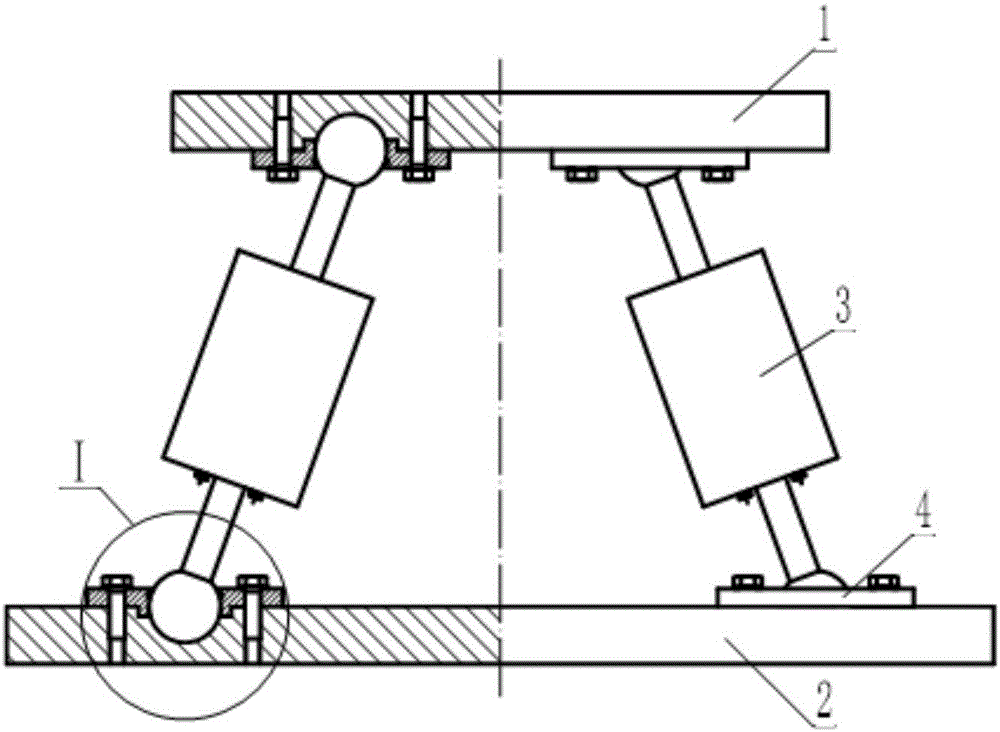
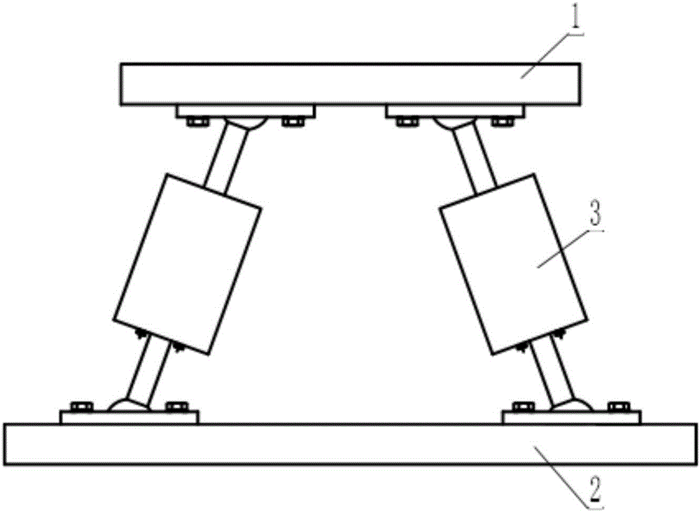
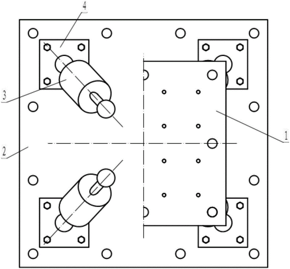
[0023] see Figures 1 to 4 , the three-dimensional isolation bearing in this example includes an upper connecting plate 1, a lower connecting plate 2 that are parallel to each other, and four pull-dry back-pressure composite spring dampers arranged between the upper connecting plate 1 and the lower connecting plate 2 3; The connecting rods 3-1 at both ends of each pull-dry back-pressure composite spring damper 3 and the upper connecting plate 1 and the lower connecting plate 2 are respectively connected by universal ball joints, forming a symmetrical side of one left and right. , The front and rear sides are symmetrical four-sided pyramid structure. The included angle between the pull-dry back-pressure composite spring damper 3 and the lower connecting plate 2 in this example is 70°.

[0024] The connecting rods 3-1 at both ends of the above-mentioned pull-dry back-pressure composite spring damper 3 are the same as the universal ball joint connection structure between the uppe...


PUM


Abstract

The invention relates to a pull rod type composite spring three-dimensional shock isolation support. The support comprises an upper connecting plate, a lower connecting plate and four pull rod back pressure type composite spring shock absorbers arranged between the upper connecting plate and the lower connecting plate, wherein the upper connecting plate and the lower connecting plate are parallel to each other. Connecting rods at the two ends of each pull rod back pressure type composite spring shock absorber are separately connected with the upper connecting plate and the lower connecting plate through universal balls to form a quadrangular frustum pyramid structure with every two opposite side faces symmetrical. The three-dimensional shock isolation support can achieve three-dimensional shock isolation in a real sense and has the effect of overturning resistance.

Description

technical field [0001] The invention relates to a building anti-vibration (or vibration) device, in particular to a three-dimensional vibration isolation device. Background technique [0002] The three-dimensional seismic isolation device is a seismic isolation device installed between the building and the foundation, which can effectively absorb and dissipate the energy input from the outside from multiple dimensions, so as to achieve the purpose of protecting the safety of the building. The three-dimensional isolation device is usually composed of a vertical isolation bearing and a horizontal isolation bearing, which absorb vertical and horizontal seismic waves respectively. [0003] As we all know, the development of three-dimensional isolation devices depends on the technical progress of dampers. At present, there are three main types of mainstream dampers that are really used in practice, namely laminated rubber dampers, metal spring dampers (mainly disc springs and co...

Claims


Application Information

Patent Timeline
Patent Type & Authority Applications(China)
IPC IPC(8): E04B1/36E04B1/98E04H9/02
CPCE04B1/36E04H9/021E04H9/023F16F1/445
Inventor 沈珊胡济福胡济全
Owner ANHUI XINZE TECH CO LTD
Why Eureka
Try Eureka