an inflow control valve

A technology of inflow control valve and valve body, which is applied in the direction of wellbore/well valve device, wellbore/well parts, sealing/packing, etc., which can solve the problems of poor oil quality and low production, and prevent water layer and gas layer penetration, increasing oil inflow, controlling production and quality effects

Active Publication Date: 2019-05-07
BEIJING UNIV OF CHEM TECH
View PDF5 Cites 0 Cited by
  • Summary
  • Abstract
  • Description
  • Claims
  • Application Information

AI Technical Summary

Problems solved by technology

[0003] The purpose of the present invention is to provide an inflow control valve that can automatically control water and gas in order to solve the problems of poor oil quality and low output in the process of producing oil in horizontal wells

Method used


Image

  • an inflow control valve
  • an inflow control valve
  • an inflow control valve

Examples


Embodiment Construction

[0020] Hereinafter, the present invention will be described in detail with reference to the accompanying drawings.

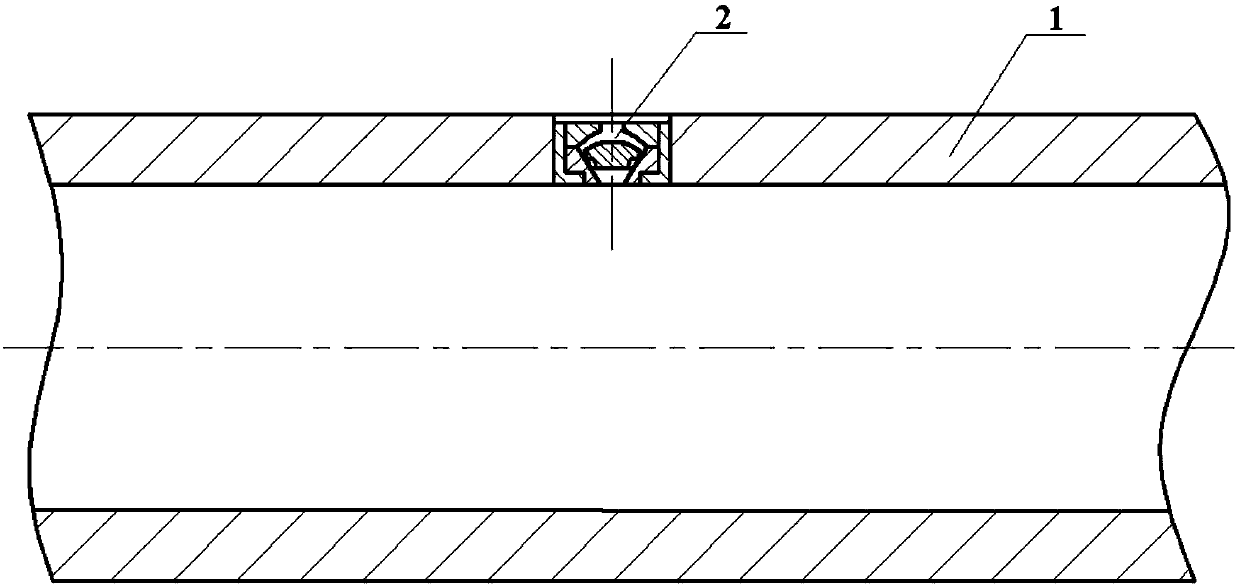
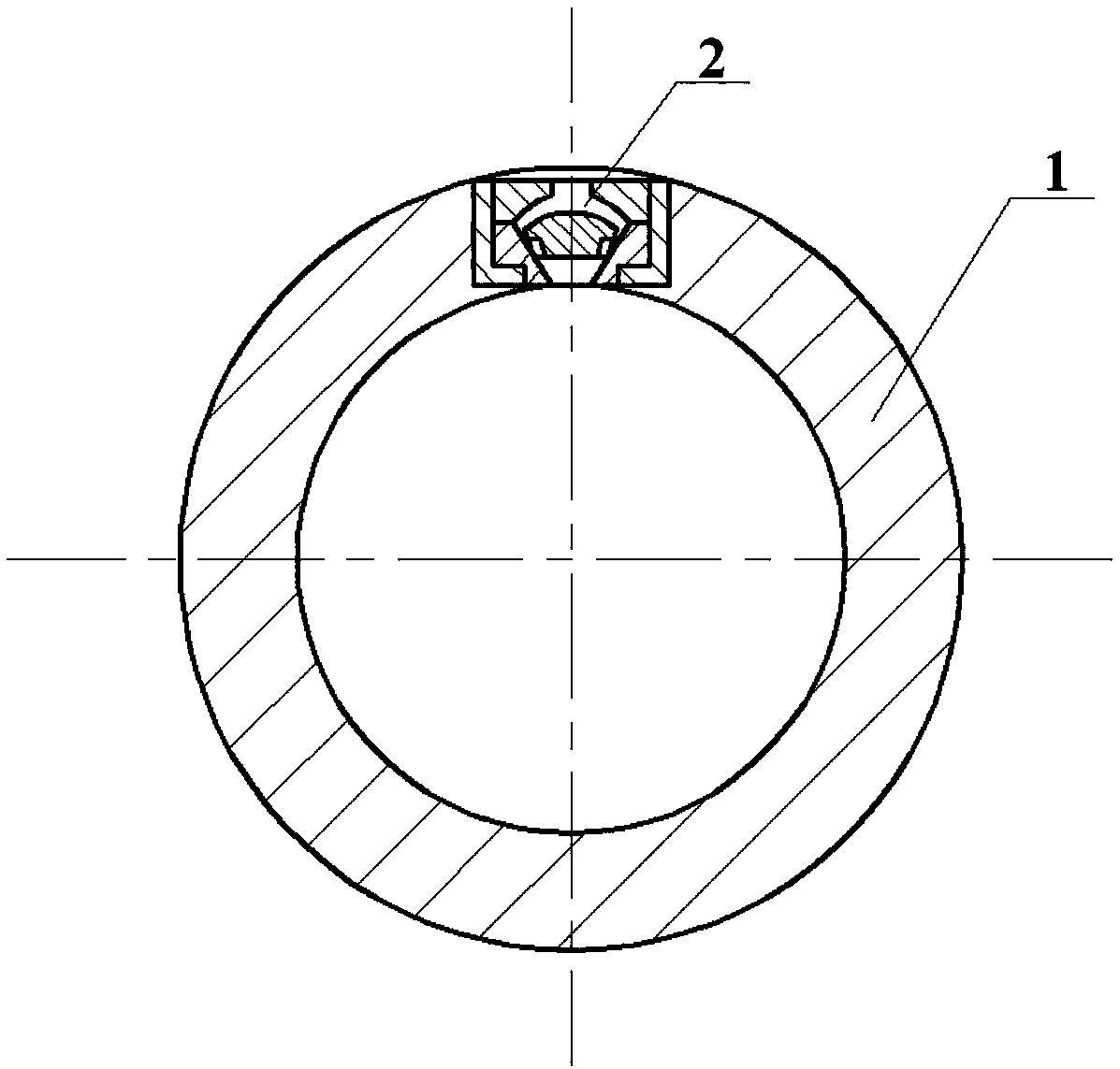
[0021] figure 1 , figure 2 A cross-sectional view of a production pipeline provided with an inflow control valve of the present invention is shown. The production pipeline 1 has a round hole, and the valve 2 is installed on the production pipeline 1 by threaded connection or expansion joint. The height of the valve 2 can vary with the thickness of the production pipeline 1. The arrangement of the valve 2 on the production pipeline 1 It can be adjusted according to different production conditions.

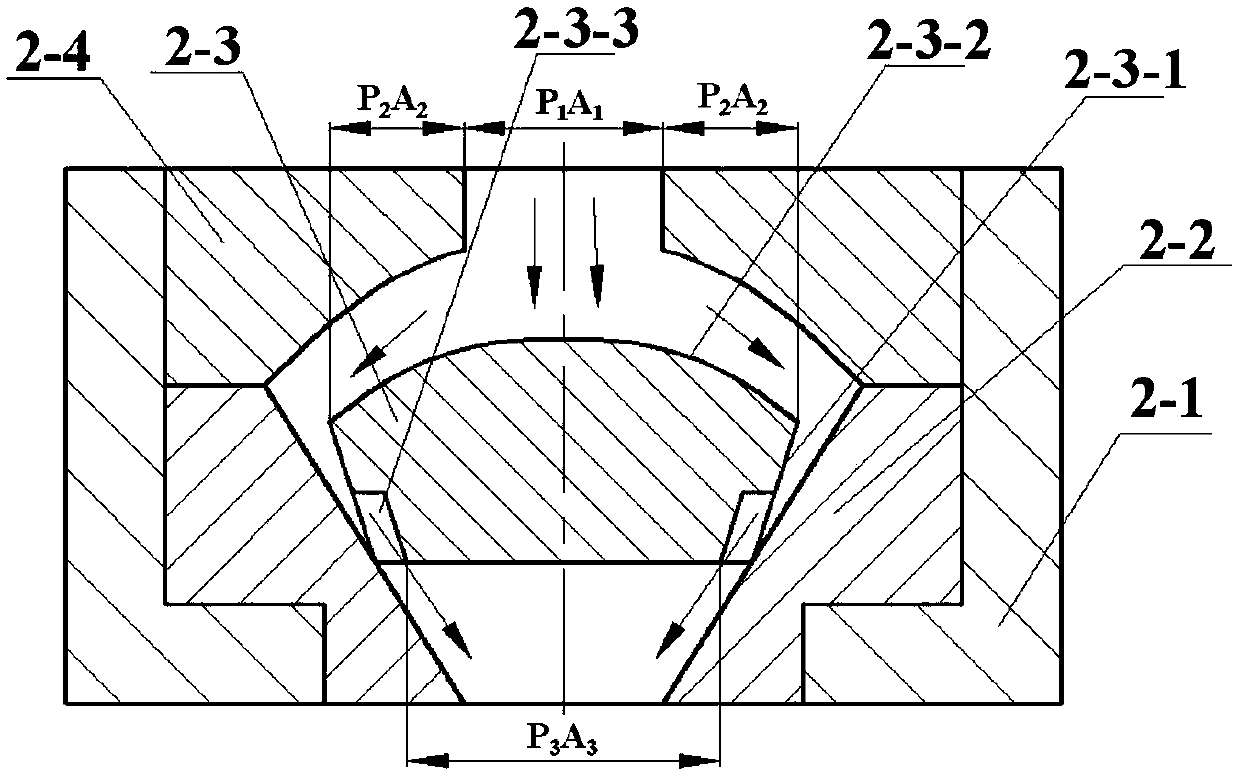
[0022] image 3 The structure of an inflow control valve of the present invention is shown. This control valve is made up of valve seat 2-1, lower valve body 2-2, spool 2-3, upper valve body 2-4. The valve seat 2-1 is installed on the production pipeline 1, and there is a stepped hole inside; the lower valve body 2-2 is embedded in the stepped hole of the valve ...


PUM


Abstract

The invention discloses a flow-in control valve which consists of a valve seat, a lower valve body, a valve core and an upper valve body, wherein the valve seat is mounted on a production pipeline; a steplike hole is formed in the valve seat; the lower valve body is embedded into the steplike hole of the valve seat; the axial position is limited by a boss; a conical hole is formed in the lower valve body; a circular hole is formed in the upper part of the upper valve body, and a curved hole is formed in the lower part of the upper valve body; the upper valve body is screwed on the valve seat in a threaded connection manner; the valve core is arranged in a space formed by the conical hole of the lower valve body and the curved hole of the upper valve body; the valve core is an entity consisting of a valve core lower conical surface, a valve core upper curved surface and valve core lower runners; the slope of the valve core lower conical surface is greater than that of the conical hole of the valve body; and the valve core lower runners are long-strip slots uniformly formed in the lower end of the valve core lower conical surface. The flow-in control valve can automatically adjust the size of a runner space of the valve according to the type of fluid and components of the fluid in a hydrocarbon reservoir, increase the flow-in amount of oil, control flow-in of water and gas and prevent water layer penetration and gas layer penetration, so that the yield and the quality of an oil product can be effectively controlled.

Description

technical field [0001] The invention relates to the field of horizontal well reservoir recovery, in particular to an inflow control valve capable of well controlling fluid mixture in an oil and gas layer to flow into a production pipeline. Background technique [0002] A horizontal well refers to a well whose inclination angle reaches or is close to 90°, and the well depth is drilled to a certain length along the horizontal direction. Generally speaking, horizontal wells are suitable for thin oil and gas layers or fractured oil and gas reservoirs, with the purpose of increasing the exposed area of ​​oil and gas layers. During the production process, due to the influence of fluid flow friction resistance, along the flow direction of the horizontal well, the pressure difference between the oil and gas layer and the production pipeline of the horizontal well changes continuously, which leads to inconsistent production rates at the upstream and downstream. In order to make the ...

Claims


Application Information

Patent Timeline
Patent Type & Authority Patents(China)
IPC IPC(8): E21B34/00
CPCE21B34/00
Inventor 谭晶何立臣张有忱丁玉梅杨卫民
Owner BEIJING UNIV OF CHEM TECH
Why Eureka
Try Eureka