
Broken filament filtering and separating device for printing and dyeing equipment

A technology for filtration separation, printing and dyeing equipment, applied in the field of printing and dyeing, can solve the problems of inconvenient maintenance, insufficient filtration, clogging of sewage treatment machines, etc., and achieve the effects of convenient filtration, simple structure and low cost

Inactive Publication Date: 2018-08-07
盛福平
View PDF0 Cites 0 Cited by
  • Summary
  • Abstract
  • Description
  • Claims
  • Application Information

AI Technical Summary

Problems solved by technology

[0002] In the traditional printing and dyeing industry, the dyeing machines used in the textile boiling and bleaching process will produce a large amount of sewage during the production process, and sewage is the main cause of the appearance of wool. The sewage treatment machine is blocked, which affects the processing. Once a fault occurs, it is inconvenient to maintain. Under the existing technology, the fluff is filtered out of the sewage, which has the disadvantage of insufficient filtration, and the current filtering method is very inefficient. After filtering, it needs to be collected and processed, therefore, the existing filtering methods need to be improved

Method used


Image

  • Broken filament filtering and separating device for printing and dyeing equipment
  • Broken filament filtering and separating device for printing and dyeing equipment

Examples


Embodiment Construction

[0014] The following will clearly and completely describe the technical solutions in the embodiments of the present invention with reference to the accompanying drawings in the embodiments of the present invention. Obviously, the described embodiments are only some, not all, embodiments of the present invention.

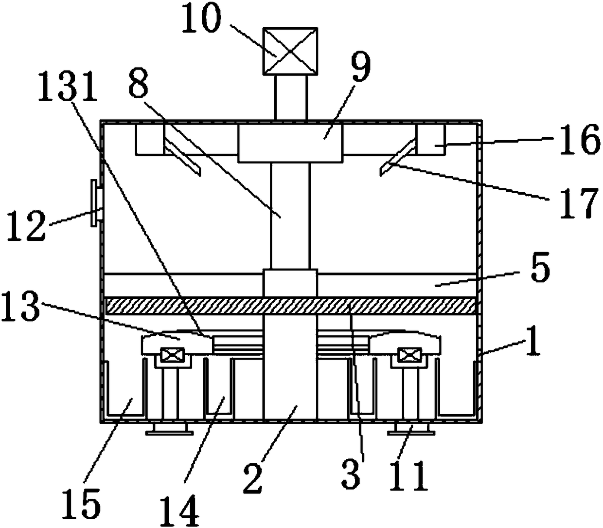
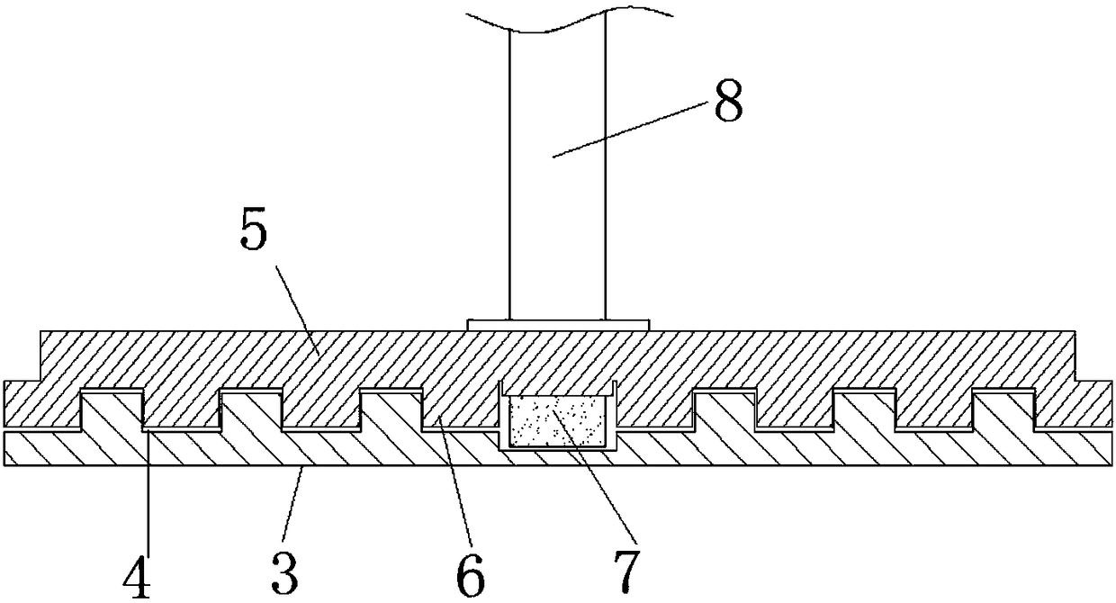
[0015] refer to Figure 1-2 , a wool filter separation device for printing and dyeing equipment, including a housing 1, a support frame 2 is welded on the bottom inner wall of the housing 1, the support frame 2 is placed vertically, and the top of the support frame 2 is installed with a first filter through screws Plate 3, the second filter plate 5 is placed on the first filter plate 3, the bottom of the second filter plate 5 is fixedly connected with the mounting seat 7 by fastening screws, the center of the second filter plate 5 is provided with a through hole, and the through hole A vertically placed rotating shaft 8 is plugged in, the bottom of the rotating shaft...


PUM


Abstract

The invention discloses a broken filament filtering and separating device for printing and dyeing equipment. The broken filament filtering and separating device comprises a shell, wherein a support frame is welded to the inner wall of the bottom of the shell and is vertically arranged, and a first filtering plate is mounted at the top of the support frame through a bolt; a second filtering plate is placed on the first filtering plate, a mounting seat is fixedly connected to the bottom of the second filtering plate through a fastening bolt, and a through hole is formed in the center of the second filtering plate; a rotating shaft is vertically placed in the through hole through plugging, the bottom of the rotating shaft penetrates through the second filtering plate, the bottom of the rotating shaft is fixed at the mounting seat, and the other end of the rotating shaft extends upwards; and a positioning plate is welded to the inner wall of the top of the shell, the rotating shaft penetrates through the positioning plate, the top of the rotating shaft extends outside the shell, and the rotating shaft is connected to the output end of a motor. The broken filament filtering and separating device is simple in structure and low in cost, broken filaments in sewage can be conveniently filtered and separated, and the device has practicability.

Description

technical field [0001] The invention relates to the technical field of printing and dyeing, in particular to a wool filter separation device for printing and dyeing equipment. Background technique [0002] In the traditional printing and dyeing industry, the dyeing machines used in the textile boiling and bleaching process will produce a large amount of sewage during the production process, and the sewage is the main cause of the appearance of wool. The sewage treatment machine is blocked, which affects the processing. Once a fault occurs, it is inconvenient to maintain. Under the existing technology, the fluff is filtered out of the sewage, which has the disadvantage of insufficient filtration, and the current filtering method is very inefficient. It needs to be collected and processed after filtering, so the existing filtering methods need to be improved. Contents of the invention [0003] The purpose of the present invention is to solve the shortcomings in the prior ar...

Claims


Application Information

Patent Timeline
IPC IPC(8): B01D29/58B01D29/03C02F1/00C02F103/30
CPCB01D29/58B01D29/03C02F1/001C02F2103/30
Inventor 盛福平
Owner 盛福平
Learn More