Heat dissipation structure of magnetic cavity in magnetic coupling homogenizer

A heat dissipation structure and homogenizer technology, applied in mixers, mixer accessories, dissolving and other directions, can solve the problems of shortened bearing service life, damage to bearings, small pressure difference of homogenizers, etc., to ensure circulation and prevent fluid leakage. Effect

Active Publication Date: 2019-10-11
安庆泰邦船舶科技有限公司
View PDF6 Cites 0 Cited by
  • Summary
  • Abstract
  • Description
  • Claims
  • Application Information

AI Technical Summary

Problems solved by technology

[0004] The technical problem to be solved by the present invention lies in: the internal magnetic rotor of the existing magnetic coupling homogenizer rotates at high speed and generates heat due to friction, the oil temperature in the inner magnetic chamber keeps rising, and the pressure difference inside the homogenizer is small, which cannot make the internal The hot oil in the magnetic cavity and the external cold oil will convect and dissipate heat, which will damage the bearing, greatly shorten the service life of the bearing, and even cause shaft fracture accidents, which will also cause demagnetization of the inner magnetic rotor

Method used


Image

  • Heat dissipation structure of magnetic cavity in magnetic coupling homogenizer
  • Heat dissipation structure of magnetic cavity in magnetic coupling homogenizer
  • Heat dissipation structure of magnetic cavity in magnetic coupling homogenizer

Examples


Embodiment 1

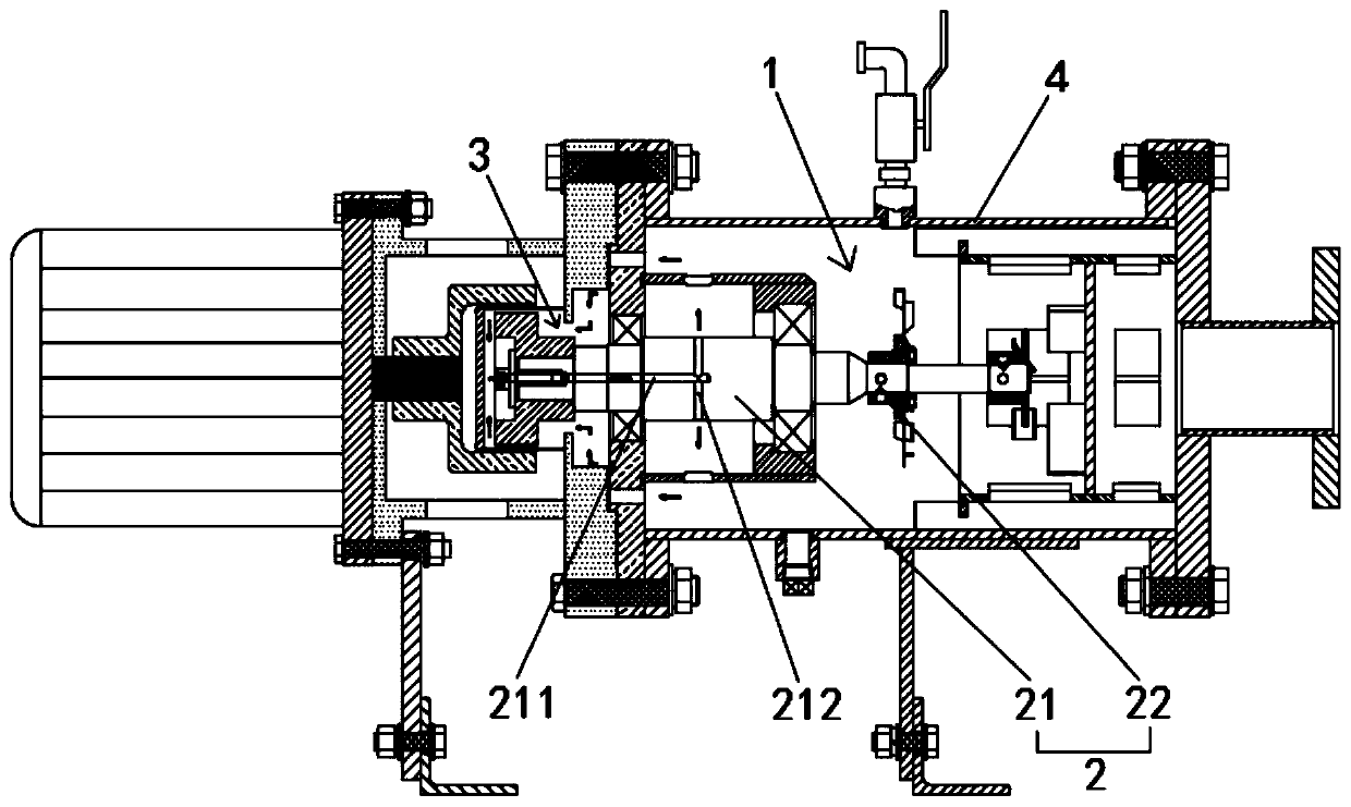
[0042] Such as figure 1 , figure 2 As shown, this embodiment discloses a heat dissipation structure of a magnetic chamber in a magnetic coupling homogenizer, including a fluid homogenization chamber 1, a homogenization transmission mechanism 2, and a fluid heat exchange chamber 3; the fluid heat exchange chamber 3 is connected to the The fluid homogeneous cavity 1 is connected, and forms a heat exchange inlet fluid channel and a heat exchange outlet fluid channel;

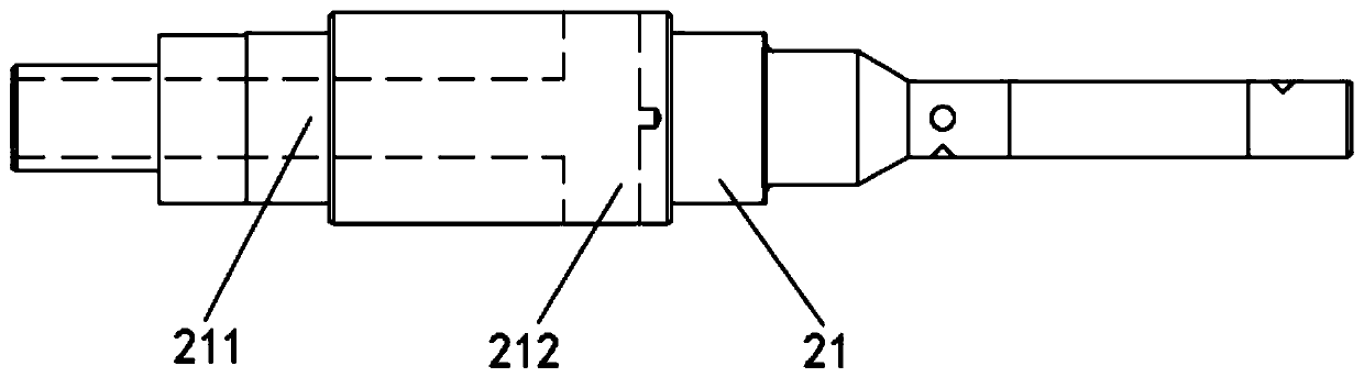
[0043] The homogeneous transmission mechanism 2 includes a main shaft 21 and a homogenizer impeller 22, and the homogenizer impeller 22 is arranged on the main shaft 21;

[0044] The terminal end of the main shaft 21 protrudes into the fluid homogeneous chamber 1 and causes the homogenizer impeller 22 to be limited in the fluid homogeneous chamber 1; the initial end of the main shaft 21 is limited in the fluid homogeneous chamber 1 In the fluid heat exchange cavity 3; the interior of the main shaft 21 is hollow,...

Embodiment 2

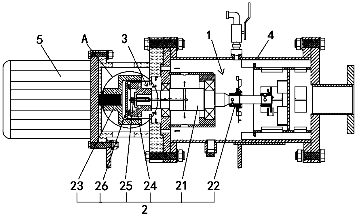
[0059] Such as Figure 4 , Figure 5 As shown, the difference between this embodiment and the first embodiment is that a spacer 26 is provided between the outer magnetic rotor 23 and the inner magnetic rotor 24, and the spacer 26 connects the outer magnetic rotor 23 and the inner magnetic rotor 24 The gap between is divided into a first gap and a second gap;

[0060] The spacer 26 is a cavity structure with one end open, and the open end of the spacer 26 is connected to the side wall of the fluid heat exchange chamber 3 to form a sealed heat exchange channel; the heat exchange channel, the second gap, the fluid The homogeneous chamber 1 is connected;

[0061]In this embodiment, the arrangement of the isolation sleeve 26 can prevent the fluid from leaking while the fluid is flowing in the fluid heat exchange cavity 3 .

[0062] Further, the head of the bolt 25 is fixed to the starting end of the inner magnetic rotor 24, and the stem of the bolt 25 is sleeved in the feed hole...

Embodiment 3

[0065] Such as image 3 , Figure 9 , Figure 10 As shown, the heat dissipation structure is integrated in the homogenizer body 4; the homogenizer body 4 is provided with a liquid inlet 41 and a liquid outlet 42; the output shaft of the motor 5 is connected to the outer magnetic rotor 23 The starting end is fixed, the liquid inlet 41 is arranged on the outer surface of the homogenizer body 4, and the liquid outlet 42 is arranged at one end of the homogenizer body 4; the other end of the homogenizer body 4 The port is also provided with a flange integrally formed with it, and the other side of the flange is also fixed with a motor connection plate, and the output end of the homogeneous transmission mechanism 2 is arranged in the cavity of the motor connection plate, and the There are also a plurality of cooling holes on the upper and lower sides of the motor connection plate, so as to facilitate the external cold air to enter the motor connection plate and exchange heat with ...


PUM


Abstract

The invention discloses a heat dissipation structure of a magnetic cavity in a magnetic coupling homogenizer. The heat dissipation structure includes a fluid homogeneous cavity, a homogeneous transmission mechanism and a fluid heat-exchange cavity; the fluid heat-exchange cavity is communicated with the fluid homogeneous cavity to form a heat-exchange fluid inlet channel and a heat-exchange fluidoutlet channel; the homogeneous transmission mechanism includes a main shaft and homogenizer impellers, and the homogenizer impellers are arranged on the main shaft; the terminal end of the main shaftextends into the fluid homogeneous cavity to make the homogenizer impellers limited in the fluid homogeneous cavity; the initiating end of the main shaft is limited in the fluid heat-exchange cavity;the main shaft is of a hollow structure, a feeding hole and a discharging hole are formed in the main shaft, the feeding hole is communicated with the heat-exchange fluid inlet channel, and the discharging hole is communicated with the heat-exchange fluid outlet channel. By making the fluid heat-exchange cavity communicated with the fluid homogeneous cavity, driving force of the homogeneous transmission mechanism enables a cold fluid in the fluid homogeneous cavity to flow into the fluid heat-exchange cavity and a hot fluid in fluid heat-exchange cavity to flow into the fluid homogeneous cavity, and through compulsory convective circulation, the purpose of heat dissipation is achieved.

Description

technical field [0001] The invention relates to the technical field of a magnetic connection homogenizer, and more specifically relates to a heat dissipation structure of a magnetic cavity in a magnetic connection homogenizer. Background technique [0002] At present, a large number of homogenizers are used in the petrochemical and shipbuilding industries. Because the homogenizer can improve the performance of fuel oil, it is more valuable in the field of heavy oil, especially in the secondary cracking of heavy fuel oil. The structure and principle of the existing homogenizers are different, but usually the working mode is driven by the motor to rotate the shaft; due to the user's higher requirements on leakage and the cost control of regular replacement of mechanical seals, the application of the magnetic connection transmission method is more and more More and more widely, therefore, technicians have constructed a transmission mode in which the motor and the homogenizer ar...

Claims


Application Information

Patent Timeline
Patent Type & Authority Applications(China)
IPC IPC(8): B01F13/08B01F15/06B01F15/00
CPCB01F33/45B01F35/40B01F2035/99B01F35/93Y02B30/00
Inventor 张志华
Owner 安庆泰邦船舶科技有限公司
Why Eureka
Try Eureka