Ink box

An ink cartridge and box body technology, which is applied in printing and other directions, can solve the problems of disconnection, air bubbles, ink waste, etc., and achieve the effects of high ink utilization rate, convenient use, and simple and feasible process.

Active Publication Date: 2015-06-24
南京绿旗喷墨技术有限公司
View PDF11 Cites 10 Cited by
  • Summary
  • Abstract
  • Description
  • Claims
  • Application Information

AI Technical Summary

Problems solved by technology

However, it does not solve the problem of large-area sponges absorbing ink and causing ink waste, nor does it solve the problem that large-area sponges will absorb a large amount of air and form bubbles during the process of mixing with ink, resulting in disconnection during printing

Method used


Image

  • Ink box
  • Ink box
  • Ink box

Examples


Embodiment 1

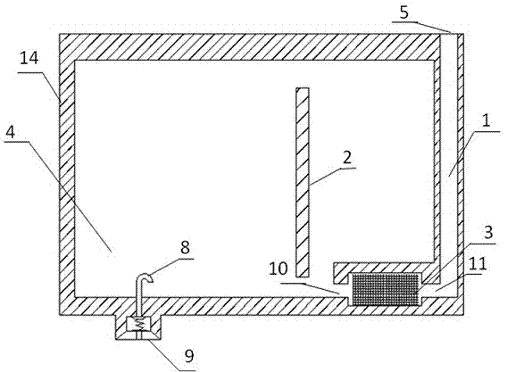
[0035] Such as figure 1 A kind of ink cartridge shown, comprises ink cartridge case body 14, ink storage chamber 4, sponge tank 3, ink filling pipeline 1, ink outlet pipeline 8, air inlet 5, ink outlet 9; Described ink storage chamber 4 is located in the middle of the ink cartridge body 14; the air inlet 5 is connected with the ink filling pipeline 1 and is located at the top of the ink cartridge; the ink outlet 9 is connected with the ink outlet pipeline 8; the sponge groove 3 is located The bottom of the ink storage chamber 4, the sponge tank 4 is a closed structure with a first air hole 10 and a second air hole 11 respectively at both ends, and a sponge is arranged inside, and the sponge tank 3 communicates with the storage tank 3 through the first air hole 10. The ink chamber 4 is connected to each other, and is connected to the ink filling pipeline 1 through the second air hole 11 .

[0036] As a further improvement of the present invention, a partition 2 is arranged in ...

Embodiment 2

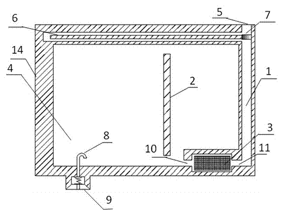
[0044] A kind of ink cartridge as shown in Figure 2, comprises ink cartridge case body 14, ink storage cavity 4, sponge tank 3, ink filling pipeline 1, ink outlet pipeline 8, air inlet 5, ink outlet 9; The ink chamber 4 is located at 14 in the ink cartridge body; the air inlet 5 is connected with the ink filling pipeline 1 and is located at the top of the ink cartridge; the ink outlet 9 is connected with the ink outlet pipeline 8; the sponge groove 3 is located at the bottom of the ink storage chamber 4. The sponge tank 4 is a closed structure with a first air hole 10 and a second air hole 11 at both ends, and a sponge is arranged inside. The sponge tank 3 passes through the first air hole 10 It is connected with the ink storage chamber 4 and connected with the ink filling pipeline 1 through the second air hole 11 .

[0045] As a further improvement of the present invention, a partition 2 is arranged in the ink storage chamber 4 .

[0046] As a further improvement of the pres...

Embodiment 3

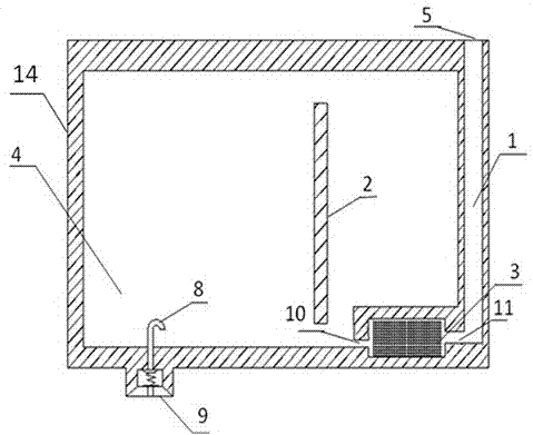
[0055] like image 3 A kind of ink cartridge shown, comprises ink cartridge case body 14, ink storage chamber 4, sponge tank 3, ink filling pipeline 1, ink outlet pipeline 8, air inlet 5, ink outlet 9; Described ink storage chamber 4 is located in the middle of the ink cartridge body 14; the air inlet 5 is connected with the ink filling pipeline 1 and is located at the top of the ink cartridge; the ink outlet 9 is connected with the ink outlet pipeline 8; the sponge groove 3 is located The bottom of the ink storage chamber 4, the sponge tank 4 is a closed structure with a first air hole 10 and a second air hole 11 respectively at both ends, and a sponge is arranged inside, and the sponge tank 3 communicates with the storage tank 3 through the first air hole 10. The ink chamber 4 is connected to each other, and is connected to the ink filling pipeline 1 through the second air hole 11 .

[0056] As a further improvement of the present invention, a partition 2 is arranged in the...


PUM


Abstract

The invention relates to an ink box, and belongs to the technical field of printing. The ink box comprises an ink box body, an ink storage cavity, a sponge groove, an ink injection pipe, an ink discharge pipe, an air intake and an ink discharge opening. The ink storage cavity is located in the ink box body. The air intake is connected with the ink injection pipe and located in the top of the ink box body. The ink discharge opening is connected with the ink discharge pipe. The sponge groove is located in the bottom of the ink storage cavity. The sponge groove is of a closed structure with the two ends provided with a first air hole and a second air hole respectively, and a sponge is arranged in the sponge groove. The sponge groove is connected with the ink storage cavity through the first air hole and connected with the ink injection pipe through the second air hole. The ink box is simple in structure, easy to machine, convenient to use, smooth in printing, capable of saving ink, not prone to leakage and reliable in performance.

Description

technical field [0001] The invention relates to an ink box and belongs to the technical field of printing. Background technique [0002] With the gradual popularization of modern office automation equipment, printers are playing an increasingly important role in people's normal work and study. Among them, inkjet printers are favored by users because of their low energy consumption, no pollution, and easy color printing. . To realize the normal use of an inkjet printer, a ink cartridge with smooth printing and difficult leakage of ink is required. In the existing technology, in order to solve the problems of unsmooth printing and ink leakage, there have been many solutions applied in production practice. There are two main solutions, one for ink cartridges that require a large area of ​​sponge material, and the other for non-sponge ink cartridges. Ink cartridges that require a large area of ​​sponge material will cause a large amount of ink to be absorbed in the sponge, ma...

Claims


Application Information

Patent Timeline
Patent Type & Authority Applications(China)
IPC IPC(8): B41J2/175
Inventor 张尚峰石欣超张阳明
Owner 南京绿旗喷墨技术有限公司
Why Eureka
Try Eureka