
Braking and cooling device of car and car

A technology of cooling device and automobile braking, applied in the direction of brake type, drum brake, brake components, etc., can solve the problems of time uncertainty of replenishing cooling water, high cost of installing retarder, hidden danger of vehicle safety, etc. Achieve the effect of good promotion and use value, simple and reliable structure, and safe operation

Active Publication Date: 2015-06-03
SINOTRUK FUJIAN HAIXI TRUCK
View PDF4 Cites 0 Cited by
  • Summary
  • Abstract
  • Description
  • Claims
  • Application Information

AI Technical Summary

Problems solved by technology

The cost of installing a retarder is too high and it is difficult to promote
[0004] In order to save costs, domestic trucks currently generally install a cooling water tank on the whole vehicle. When braking, open the valve of the cooling water tank, and cold water will be sprayed on the brake drum, which can reduce the temperature of the brake pads and delay the brake system. Heat decay, but the system needs to add cooling water to the water tank from time to time, which is inconvenient to use
And the uncertainty of the time to supplement the cooling water also brings a great potential safety hazard to the system
At the same time, the cooling water and the brake drum will flow directly on the road after heat exchange. In the cold winter, the water will freeze and freeze quickly, which brings a huge safety hazard to the vehicles driving behind.

Method used


Image

  • Braking and cooling device of car and car
  • Braking and cooling device of car and car

Examples


Embodiment Construction

[0017] In order to describe the technical content, structural features, achieved goals and effects of the present invention in detail, the following will be described in detail in conjunction with the embodiments and accompanying drawings.

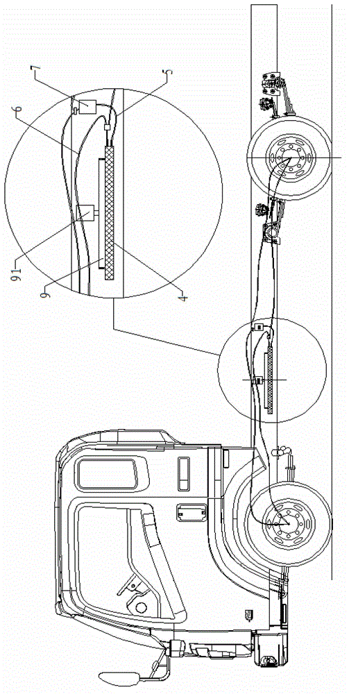
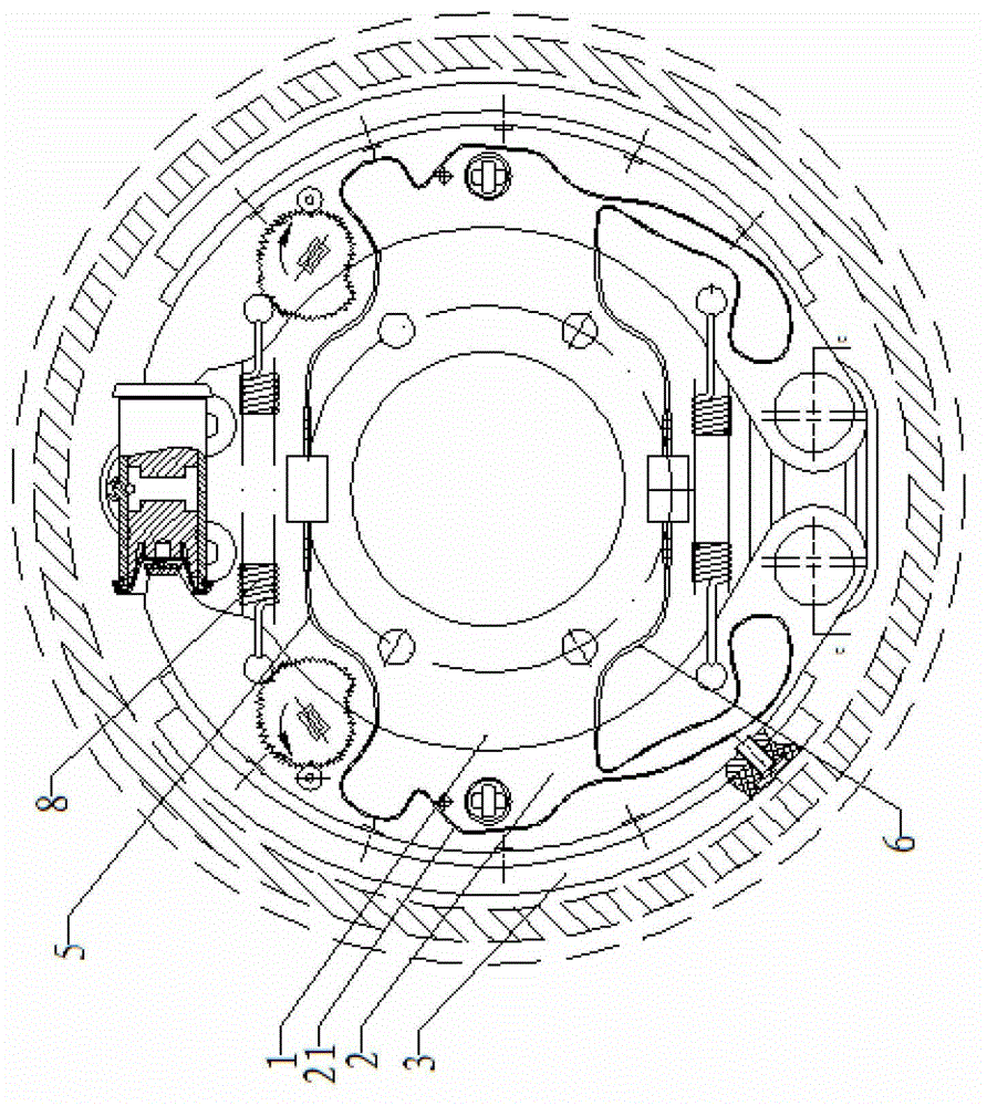
[0018] see figure 1 and attached figure 2 , as shown in the accompanying drawings, an automobile brake cooling device provided by the present invention is used for cooling the brake system, including a brake assembly and a cooling water circulation assembly, the brake assembly is arranged inside the hub, and the brake The assembly includes a brake floor assembly 1 and two brake shoes 2 and two brake pads 3 arranged on the brake floor assembly 1. The brake shoes 2 are symmetrically arranged on the inner side of the hub, and the two brake shoes 2 One end is hinged on the brake floor assembly 1 through a pin shaft, and the other end is controlled by a driving mechanism to rotate the brake shoe 2 around the pin shaft. The outer side of the b...


PUM


Abstract

The invention discloses a braking and cooling device of a car, which is used to brake a hub and comprises a brake component and a cooling water circulating component; wherein the brake component is arranged at the inner side of the hub and comprises a brake bottom plate assembly as well as two brake shoes and two brake pads which are arranged on the brake bottom plate assembly; the brake shoes are arranged symmetrically at the inner side of the hub; one end of each of the two brake shoes is hinged on the brake bottom plate assembly through a pin shaft, and the other end of each of the two brake shoes is used for controlling the brake shoes to rotate around the pin shaft through a drive mechanism; the brake pads are arranged at the outer sides of the brake shoes, and the brake shoes are provided with water flow passages; the cooling water circulating component comprises a water tank, a water outlet pipe, a water inlet pipe and a water pump; a water outlet and a water inlet are arranged in the water tank; the water outlet is connected with the water outlet pipe which is connected with one end of the water flow passage, and the other end of the water flow passage is connected with the water inlet through the water outlet pipe. According to the braking and cooling device, the circulation of the entire water flow is controlled by a water pump to realize the stable operation of the system, thereby avoiding the phenomenon of ineffective brake due to excessively high temperature of the brake system.

Description

technical field [0001] The invention relates to the field of auto parts, in particular to an automobile brake cooling device for slowing down the phenomenon of brake heat attenuation during the braking process of an automobile, and an automobile using the brake cooling device. Background technique [0002] When the vehicle braking system works under heavy load for a long time, the friction between the brake friction plate and the wheel drum will generate high temperature, so that the braking force will be reduced sharply, that is, the phenomenon of thermal attenuation of the braking system will appear. Brake heat attenuation refers to the phenomenon that the brake braking force attenuates after the brake system generates high temperature due to the strong friction between the brake disc or the brake hub and the brake pad. The braking performance of the braking system under high heat conditions will be greatly weakened, and if the temperature exceeds the limit, it will cause ...

Claims


Application Information

Patent Timeline
Patent Type & Authority Patents(China)
IPC IPC(8): F16D65/833F16D51/20F16D51/24
Inventor 田荣周庆金
Owner SINOTRUK FUJIAN HAIXI TRUCK
Learn More