
Demountable microtube array heat transfer performance tester

A heat transfer performance and test device technology, applied in the field of heat transfer, can solve the problems of non-reusable test device, increase test cost, and difficult processing, etc., achieve the effect of convenient disassembly and assembly, easy disassembly and assembly, and guaranteed sealing effect

Inactive Publication Date: 2017-05-31
NANJING UNIV OF TECH
View PDF7 Cites 0 Cited by
  • Summary
  • Abstract
  • Description
  • Claims
  • Application Information

AI Technical Summary

Problems solved by technology

However, the heat transfer performance test of the micropipe array needs to separate the fluid inside the tube (tube side) and the fluid outside the tube (shell side). Generally, brazing and other methods are used to connect the micropipe and the tube sheet, which is difficult to process and the test device cannot be repeated. Utilize, increase test cost

Method used


Image

  • Demountable microtube array heat transfer performance tester
  • Demountable microtube array heat transfer performance tester
  • Demountable microtube array heat transfer performance tester

Examples


Embodiment 1

[0049] Embodiment 1: Structure and principle of micropipe array heat transfer performance test device of the present invention

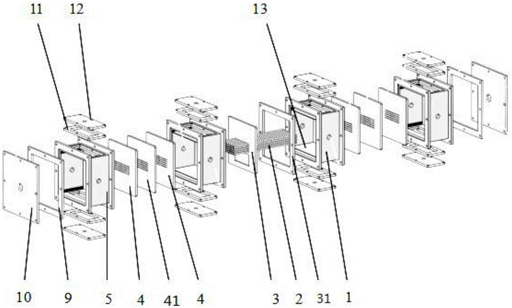
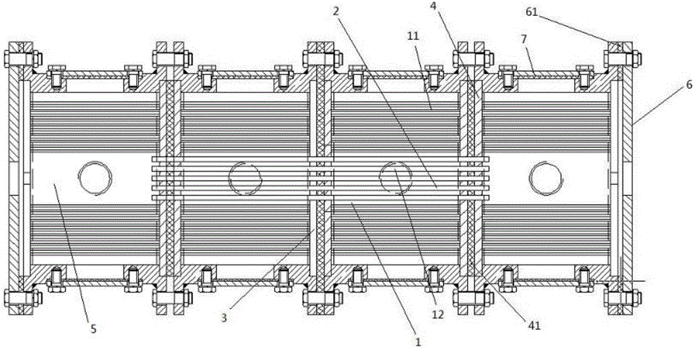
[0050] Such as figure 1 , figure 2 As shown, the micropipe array heat transfer performance test device of the present invention is divided into a tube side and a shell side, wherein the shell side is mainly composed of a plurality of cylinder sections 1 connected to each other, and an end cylinder section 5 is respectively arranged at both ends of the shell side, The outer end of the end cylinder section 5 is sealed by the end cover 6, and the end cylinder section 5 communicates with the heat exchange tube 2 that is sheathed in the shell side to form a tube side.

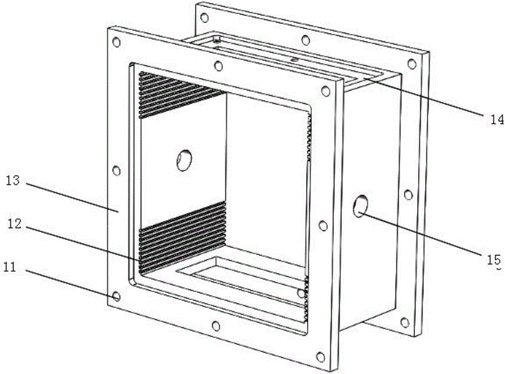
[0051] The cylindrical section 1 and the end cylindrical section 5 in the shell side have the same shape and structure, and are rectangular tubes, such as image 3 , The two ends of the barrel section are provided with flanges 13 with the same shape as the barrel section, and the barrel...

Embodiment 2

[0057] Embodiment 2: Design and processing of the main components of the micropipe array heat transfer performance test device

[0058] According to different experimental requirements, the size of the cylinder section also has different requirements. The specific determination steps are as follows:

[0059] The size of the barrel joint includes the side length and axial length of the barrel joint. The specification of heat exchange tubes (inner diameter and outer diameter), heat transfer area and volume flow rate of tube-side fluid are taken as the initial conditions for the design of the tube section.

[0060] First, according to the formula:

[0061]

[0062] and the formula:

[0063]

[0064] To determine the number and length of heat exchange tubes. (where n s - the number of heat exchange tubes; V - the volume flow rate of the tube side fluid; d i ―the inner diameter of the heat exchange tube; u i ―The flow rate of the fluid in the heat exchange tube; L—the l...

Embodiment 3

[0077] Embodiment 3: the assembly example of micropipe array heat transfer performance testing device of the present invention

[0078] The micropipe array heat transfer performance test device of the present invention is made up of four tube joints, will be as Figure 13 The test device composed of four equal-length barrel joints shown is one of the installation examples, and the specifications of the barrel joints are as follows: Figure 14 , 15 shown. Among them, the middle two shell-side cylinder sections 2 and 6 are connected to form the shell-side, and the shell-side is provided with a heat exchange tube 4; the two end cylinder sections 10 and 21 on both sides are used as the tube-side tube boxes of the test device for heat exchange. The inlet and outlet of the pipe extend into the barrel sections on both sides respectively, forming a tube path together with the end barrel sections.

[0079] During installation, the two cylinder sections 2 and 6 are firstly connected ...


PUM

PropertyMeasurementUnit
diameteraaaaaaaaaa

Abstract

The invention provides a demountable microtube array heat transfer performance tester which is convenient to dismount and with main parts repeatedly usable. The equipment comprises a shell side and a tube side. The shell side is formed by connecting several shell rings. A baffle plate is arranged between adjacent shell rings. Two ends of the shell side are respectively connected to an end shell ring, the outer end of which is sealed by an end cap. A heat exchange tube which is sleeved inside the shell rings of the shell side is respectively communicated with end shell rings at the two ends so as to form the tube side. The junction between the shell ring of the shell side and the end shell ring of the tube side is separated through a tube plate. The middle parts of the tube plate and the baffle plate are both provided with several circular holes with diameter consistent with diameter of the heat exchange tube. The heat exchange tube interpenetrates the circular holes. a rectangular hole used for flowing of a fluid is arranged below a circular hole area of the baffle plate. The shell side and the tube side are both provided with a liquid inlet and a liquid outlet. The invention has the following beneficial effects: the tester of the invention is convenient to dismount, and repeated utilization rate of various parts is enhanced. By changing the number of the shell rings, the requirement of the shell side's length is met, and different testing requirements are met.

Description

technical field [0001] The invention belongs to the technical field of heat transfer, and relates to a micropipe array heat transfer performance test device. Background technique [0002] With the development of micro-processing technology and its application in biochips, micro-electronic machinery and analytical instruments, the problem of micro-scale transmission has become the focus of research in various countries. At the 8th National Conference on Heat Transfer in the UK, microscopic heat and mass transfer issues became a hot topic of discussion; at the second US-Japan Joint Symposium, Professor Tian Changlin from the University of California made a presentation on "Molecular and Microscale Transport Phenomena". Important academic report. The miniaturization of the delivery system has brought new challenges to the traditional chemical engineering discipline, and at the same time injected new vitality into the development of the discipline. As the size of the system sh...

Claims


Application Information

Patent Timeline
Patent Type & Authority Applications(China)
IPC IPC(8): G01N25/18
CPCG01N25/18
Inventor 周剑锋杨博朝范浩亮任政张浩王铮张康帅于秋楠陈丽君
Owner NANJING UNIV OF TECH
Learn More