
Laser marking machine

A laser marking machine, laser technology, applied in the field of laser marking machines

Inactive Publication Date: 2017-03-01
周利英
View PDF0 Cites 0 Cited by
  • Summary
  • Abstract
  • Description
  • Claims
  • Application Information

AI Technical Summary

Problems solved by technology

[0002] The known laser marking machine is composed of a laser generator, a focusing lens and a marking table, and the biggest disadvantage is that it can only be used in the factory

Method used


Image

  • Laser marking machine

Examples


Embodiment Construction

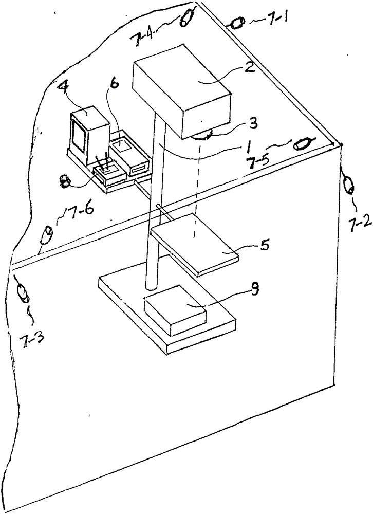
[0010] In the accompanying drawings, a corner of indoor and outdoor is easily illustrated with a transparent wall, the outdoor network cameras (7-1, 7-2, 7-3) are outdoors, and the indoor network cameras (7-4, 7-5, 7- 6) Indoors, the laser marking machine (1) consists of a laser generator (2), a focusing lens (3) and a marking table (5). A server (6), multiple A network camera (7) and a plurality of security devices, the server (6) is connected to the Internet, and the server (6) and the network camera (7) are connected with a WIFI (8) network or a wired network. The server (6) receives the video and audio signals of the network camera (7) and compresses and stores them in the server (6) or transfers them to a remote server for backup. The server (6) allows the authorized person to remotely connect to multiple network cameras (7) in real time, The server (6) receives the alarm signal from the network camera (7) and the security equipment and notifies relevant personnel in real...


PUM


Abstract

A laser marking machine is provided with a server, a plurality of network cameras and a plurality of security and protection devices. The server is connected with the Internet. The server is connected with the network cameras through a WIFI network or a wired network. The server receives video signals of the network cameras and compresses, stores or forwards the video signals to a remote server so that the video signals can have backups. The server allows an authorizer to remotely connect the multiple network cameras in real time. The server receives alarm signals of the network cameras and the security and protection devices and notifies concerned personnel to take disaster destroying measures in real time. The multiple network cameras are arranged at indoor corners and outdoor periphery, monitor indoor and outdoor security situations in real time and transmit videos to the server and a displayer through the WIFI network or the wired network in real time so that video storing and security and protection monitoring can be carried out. The network cameras can be provided with sensors at the same time, the device cost is reduced, and the security and protection effects are enhanced. The laser marking machine is provided with the server and the network cameras, can remotely carry out marking and automatically carry out vending and can also serve as a security and protection command center, and the laser marking machine has multiple functions.

Description

technical field [0001] The invention relates to a laser marking machine, which is equipped with a server, a network camera and security equipment, and has increased functions. Background technique [0002] The known laser marking machine is composed of a laser generator, a focusing lens and a marking table, and it can only be used in factories, which is the biggest disadvantage. Contents of the invention [0003] In order to overcome the disadvantages of known laser marking machines, the present invention provides a laser marking machine capable of remotely controlling security equipment. [0004] The technical solution adopted by the present invention to solve its technical problems is: set up a server, a plurality of network cameras and a plurality of security devices on the laser marking machine, the server is connected to the Internet, and the server and the network cameras are connected by a WIFI network or a wired network. connection. The server receives the video ...

Claims


Application Information

Patent Timeline
IPC IPC(8): B23K26/362G08B19/00
CPCG08B19/00
Inventor 周利英
Owner 周利英
Learn More