Switch assembly for use in a power transmission system

A technology for switching components and frequencies, applied in the field of power systems, can solve problems such as exposure of solid-state semiconductor devices

Active Publication Date: 2017-03-08
HITACHI ENERGY SWITZERLAND AG
View PDF4 Cites 4 Cited by
  • Summary
  • Abstract
  • Description
  • Claims
  • Application Information

AI Technical Summary

Problems solved by technology

This can expose solid-state semiconductor devices to continuous current stress, which can be relatively high especially in HVDC applications

Method used


Image

  • Switch assembly for use in a power transmission system
  • Switch assembly for use in a power transmission system
  • Switch assembly for use in a power transmission system

Examples


Embodiment Construction

[0049] Hereinafter, the present invention will now be described with reference to the accompanying drawings, in which exemplary embodiments of the invention are shown. This invention may, however, be embodied in many different forms and should not be construed as limited to the embodiments set forth herein; rather, these embodiments are provided by way of example so that this disclosure will convey the scope of the invention to those skilled in the art.

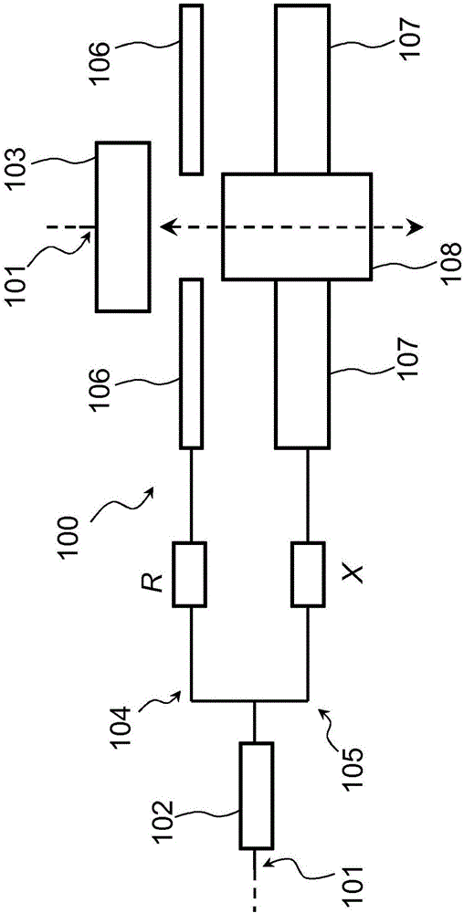
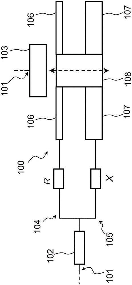
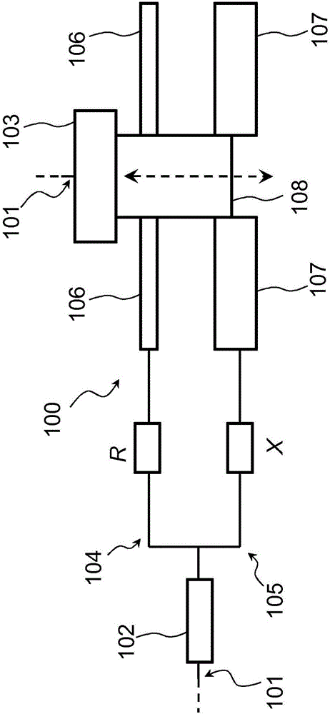
[0050] now refer to Figure 1-3 , shows a schematic cross-sectional side view of a switch assembly 100 according to an embodiment of the present invention.

[0051] The switch assembly 100 is used to switch between the first electrical conductor 102 and the second electrical conductor 103 Figure 1-3 used in the circuit indicated by the partially dashed line 101. The electrical circuit 101 is configured to carry an electrical current between the first electrical conductor 102 and the second electrical conductor 103, the elect...


PUM


Abstract

A switch assembly (100) is disclosed for use in a circuit (101) configured to carry a current between a first electrical conductor (102) and a second electrical conductor (103). The switch assembly comprises at least a first current path (104) and a second current path (105) each of which includes an electrical contact (106, 107) which can be selectively connected to or disconnected from the second electrical conductor (103). At least one of the first current path (104) and the second current path (105) is configured such that it has a frequency-dependent reactance or impedance so as to force or cause current with a frequency which complies with a selected frequency criterion and which flows between the first electrical conductor (102) and the second electrical conductor (103) to flow, at least to a greater extent, via a selected one of the first current path (104) and the second current path (105).

Description

technical field [0001] The present invention generally relates to the field of power systems such as power distribution or transmission systems, for example high voltage direct current (HVDC) power transmission systems. In particular, the present invention relates to a switch assembly for use in an electrical circuit between a first electrical conductor and a second electrical conductor, the electrical circuit being configured to carry electrical current between the first electrical conductor and the second electrical conductor. Background technique [0002] Power systems such as power distribution or transmission systems are used to supply, transmit and use electricity. High voltage direct current (HVDC) power transmission is becoming increasingly important due to the increased demands on power transmission and distribution systems for power supply or delivery and interconnection. A power system, such as a power distribution or transmission system, typically includes a pro...

Claims


Application Information

Patent Timeline
Patent Type & Authority Applications(China)
IPC IPC(8): H02M1/32H01H39/00H01H87/00
CPCH01H39/004H01H87/00H02M1/32H02M7/003H02M1/0064H02M7/4835H02H7/20
Inventor E·多雷O·杰普森
Owner HITACHI ENERGY SWITZERLAND AG
Why Eureka
Try Eureka