Video conversation recording method and device
A technology of video call and recording method, which is applied in the direction of TV, image communication, color TV, etc., and can solve the problem that the user cannot view the content of the call
- Summary
- Abstract
- Description
- Claims
- Application Information
AI Technical Summary
Problems solved by technology
Method used
Image

Examples
Embodiment Construction
[0072] Reference will now be made in detail to the exemplary embodiments, examples of which are illustrated in the accompanying drawings. When the following description refers to the accompanying drawings, the same numerals in different drawings refer to the same or similar elements unless otherwise indicated. The implementations described in the following exemplary examples do not represent all implementations consistent with the present disclosure. Rather, they are merely examples of apparatuses and methods consistent with aspects of the present disclosure as recited in the appended claims.
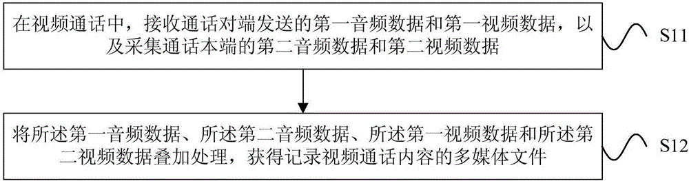
[0073] figure 1 is a flow chart of a video call recording method shown according to an exemplary embodiment, as shown in figure 1 As shown, the video call recording method is used in a terminal, and includes the following steps.
[0074] In step S11, in the video call, the first audio data and the first video data sent by the calling end are received, and the second audio data and th...
PUM
 Abstract
Description
Claims
Application Information
PatSnap Eureka turns technology decisions into work you can execute. Powered by our Innovation Knowledge Graph, it runs expert workflows across engineering, life sciences, materials and intellectual property. Get your review-ready output in minutes.


