Multi-plate wet clutch oil pressure control system of hydrodynamic transmission

A technology of wet clutch and hydraulic transmission, applied in the direction of transmission control, elements with teeth, fluid pressure actuating devices, etc., can solve the problems of high maintenance cost, easy damage, and many influencing factors, and achieve high maintenance cost. , The effect of reducing power interruption time and less interference factors

Inactive Publication Date: 2017-03-22
贵州凯星液力传动机械有限公司
View PDF4 Cites 4 Cited by
  • Summary
  • Abstract
  • Description
  • Claims
  • Application Information

AI Technical Summary

Problems solved by technology

[0004] The present invention aims to provide a multi-disc wet clutch oil pressure control system of a hydraulic transmission to solve the problems of large number of parts, easy damage, and the influence of the control process in the existing hydraulic transmission that uses an electronic control system for oil pressure control There are many factors, high requirements on software, machining accuracy and oil cleanliness, high maintenance costs and small application range, etc.

Method used


Image

  • Multi-plate wet clutch oil pressure control system of hydrodynamic transmission
  • Multi-plate wet clutch oil pressure control system of hydrodynamic transmission
  • Multi-plate wet clutch oil pressure control system of hydrodynamic transmission

Examples


Embodiment 1

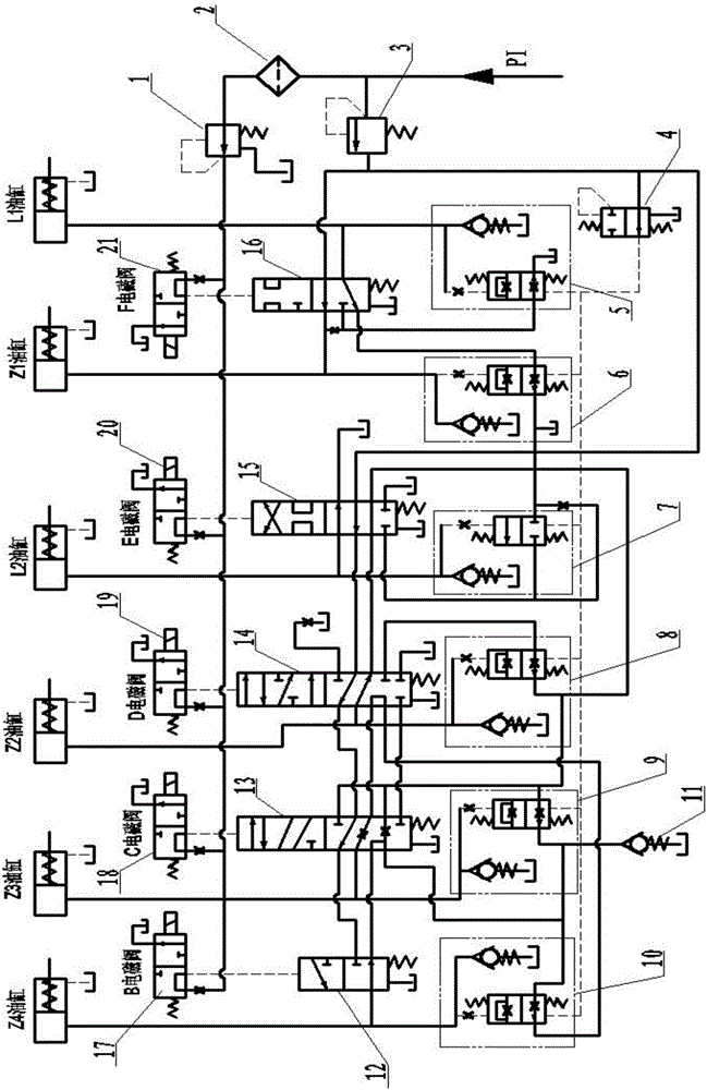
[0026] Embodiment 1: as figure 1 As shown, when the power is not on, the main oil circuit PI is divided into two circuits, one of which goes through the filter screen 2 to the electromagnetic pressure regulating valve 1, so as to supply oil to the pilot proportional solenoid valve B17 ~ pilot proportional solenoid valve F21, and the oil pressure enters the two-position multi-way The top of the reversing spool valve A12~two-position multi-way reversing spool valve E16, so that the spool valve core is located at the lower part, and the control oil passages of each clutch are in the state of draining oil; the other way goes to the priority valve 3, passes through two Pass reversing slide valve A12 to two-position multi-pass reversing slide valve E16, ready to supply oil to the clutch oil cylinder.

[0027] After the power is turned on, one or two of the pilot proportional solenoid valve B17 ~ pilot proportional solenoid valve F21 is energized, and the corresponding two-position m...

Embodiment 2

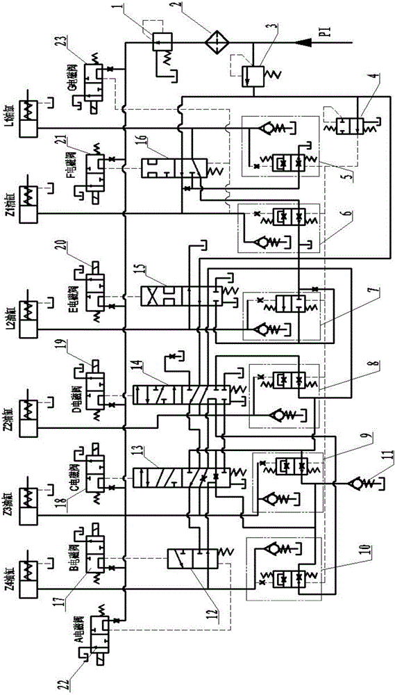
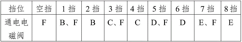
[0035] Embodiment 2: A solenoid valve is added at the bottom of the slide valve spool to realize the locking gear function, such as figure 2 As shown, solenoid valve A22 and solenoid valve G23 are added, and the power is energized as shown in Table 4, which can realize the function of locking the gear when the power is suddenly cut off during work. According to the gear requirements of the transmission, the number of pilot solenoid valves can be reduced to reduce the gear.

[0036] Table 4

[0037]

[0038] In order to improve the response speed of each valve, the spool of each reversing spool valve is made of lighter aluminum alloy material, and the surface of the spool is hard anodized to improve the wear resistance.


PUM


Abstract

The invention discloses a multi-plate wet clutch oil pressure control system of a hydrodynamic transmission. The multi-plate wet clutch oil pressure control system comprises a main oil way, wherein the downstream of the main oil way is divided into a servo oil way and a working oil way, the servo oil way comprises an electromagnetic pressure regulating valve, five electromagnetic valves and five reversing slide valves which are connected in series in sequence, and the working oil way comprises a priority valve, a buffer pressure regulating valve, six buffer valves and six clutch cylinders which are connected in series in sequence. According to the multi-plate wet clutch oil pressure control system, a plurality of electromagnetic valves, shift valves and buffer valves are used for performing process control over the oil pressure of a clutch, a gear locking function is added, gear shifting protection is performed by hardware, interference factors are less, and the power interruption time during gear shifting is reduced as far as possible.

Description

technical field [0001] The invention relates to the technical field of hydraulic transmission control, in particular to the technical field of hydraulic control of hydraulic transmissions, in particular to a multi-plate wet clutch oil pressure control system of a hydraulic transmission. Background technique [0002] The multi-plate wet clutch oil pressure control system of hydraulic transmission is the key technology of hydraulic transmission shift control, which is related to the shift quality and life of hydraulic transmission. At present, the clutch oil pressure control of various hydraulic transmissions mostly adopts the pilot proportional or high-speed switch solenoid valve to provide pilot control oil pressure, and provides control signals to the solenoid valve under the control of the software of the electronic control unit to control the pilot oil pressure. Then use this pilot oil pressure to control the reversing spool valve to provide oil pressure for the clutch to...

Claims


Application Information

Patent Timeline
Patent Type & Authority Applications(China)
IPC IPC(8): F16H61/28F15B11/16F15B13/06
CPCF15B11/16F15B13/06F16H61/2807
Inventor 张芳张正富邓航邓炜
Owner 贵州凯星液力传动机械有限公司
Why Eureka
Try Eureka