A hybrid system clutchless synchronous shift control method and system

A hybrid system, clutch synchronization technology, applied in hybrid vehicles, motor vehicles, transportation and packaging, etc., can solve the problems of increased switching time, long power interruption time, high cost, and achieve cost reduction and power interruption time reduction. Effect

Active Publication Date: 2021-06-15
江苏新能源汽车研究院有限公司
View PDF10 Cites 0 Cited by
  • Summary
  • Abstract
  • Description
  • Claims
  • Application Information

AI Technical Summary

Problems solved by technology

[0007] 1. The clutch is used, which increases the switching time and the power interruption time is long;
[0008] 2. The hydraulic control system of the clutch has problems such as sealing, and the cost is relatively high

Method used


Image

  • A hybrid system clutchless synchronous shift control method and system
  • A hybrid system clutchless synchronous shift control method and system
  • A hybrid system clutchless synchronous shift control method and system

Examples


Embodiment 1

[0087] Such as the above shift control method, wherein,

[0088] Shift force F=200N, make the engine close to zero torque mode,

[0089] The half cone angle of the synchronous ring cone surface is 7°, the locking angle is 51°,

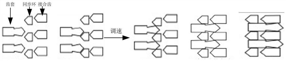
[0090] Such as Figure 5 As shown, the rotating speed of the engaging gear w=1000rpm, the rotating speed of the gear sleeve is 960rpm, the speed regulating motor regulates the engine speed, so that the rotating speed w of the engaging gear decreases with a certain slope. The speed crossing occurs at 150 ms, and the displacement of the gear sleeve changes greatly after the speed crossing point of the engaging tooth and the gear sleeve. It shows that the speed control system actively controls the rotation speed of the engaging teeth to make it cross with the rotating speed of the gear sleeve. At this time, the synchronous ring will open the shift opportunity window, and the gear sleeve can pass through the synchronous ring to complete the meshing with ...

Embodiment 2

[0092] The magnitude of the shifting force F is: F=150N, making the engine close to the zero torque mode,

[0093] The half cone angle of the synchronous ring cone is 6°30’, the locking angle is 52°,

[0094] Such as Figure 6 As shown, the rotational speed of the engaging gear w=2000rpm, and the rotating speed of the gear sleeve is 1960rpm. The speed regulating motor regulates the engine speed so that the rotational speed w of the engaging gear decreases with a certain slope. The speed crossing occurs at 160ms, and the displacement of the gear sleeve changes greatly after the speed crossing point of the engaging tooth and the gear sleeve. By simulating the different angular relationships of the gear sleeves and engaging teeth when meshing, both gear shifts can be achieved. It shows that the speed control system actively controls the rotation speed of the engaging teeth to make it cross with the rotating speed of the gear sleeve. At this time, the synchronous ring will open ...


PUM


Abstract

The invention discloses a hybrid power system clutchless synchronous shift control method and system, comprising the following steps: S1 obtains the shift demand, S2 enters the shift preparation, and the synchronous ring is protected when the speed of S3 is different, under the action of the shift motor , the tooth sleeve advances, when it touches the synchronous ring, due to the speed w of the engaging tooth 1 and gear bushing speed w 2 Different, the synchronous ring is subjected to the friction torque of the engaging teeth and the ring torque of the gear sleeve, and the friction torque is greater than the torque of the dial ring, so that the gear sleeve cannot drive the synchronous ring to move, and the gear sleeve cannot pass through the synchronous ring and combine with the engaging teeth; after S4 speed regulation To shift gears, S5 mounts a new gear, resumes torque output, and S6 executes a new round of gear shifting cycle. The clutchless synchronous shift control system of the hybrid power system includes an execution unit, an automatic transmission controller, a shift motor, a hybrid power system, and a synchronous ring. The present invention avoids using a clutch when shifting gears, thereby reducing costs and power interruption time.

Description

technical field [0001] The invention belongs to the technical field of gear shift control of a hybrid power system of a new energy vehicle, and in particular relates to a clutchless synchronous gear shift mechanism and a gear shift strategy of a new energy hybrid power system during hybrid power coupling and gear shifting. Background technique [0002] Hybrid electric vehicles use the characteristics of low-speed constant torque and high-speed constant power of the motor, and cooperate with the internal combustion engine. Through the switching of power coupling mode and gearbox speed ratio, the system power of the vehicle can be used most effectively for various driving scenarios, improving Fuel economy and reduced emissions, combined with the dual advantages of power and economy, is a better choice at this stage. [0003] Most hybrid coupling mechanisms add motors to the structure of traditional DCT, AT and CVT gearboxes, such as the Geely Lynk & Co P2 / P2.5 system, BYD P2 a...

Claims


Application Information

Patent Timeline
Patent Type & Authority Patents(China)
IPC IPC(8): B60W10/11B60W10/06B60W10/08B60W30/19B60W20/10
CPCB60W10/06B60W10/08B60W10/11B60W20/00B60W30/19B60W2510/0638B60W2520/10Y02T10/62
Inventor 邹大庆孙畅宋永亮石放辉蒋宇翔夏乐春沈双达刘汪洋陈曦林联杰
Owner 江苏新能源汽车研究院有限公司
Why Eureka
Try Eureka