Supercharge Your Innovation With Domain-Expert AI Agents!

A self-locking channel steel rail clamp

A technology of channel steel track and rail clamp, which is applied in the direction of load hanging components, building material processing, construction, etc., can solve the problems of insufficient smoothness of the sliding process, increase of engineering construction amount, jumping of rail clamp, etc., and achieve the goal of purchasing Convenience, short working cycle, small clamping surface slope

Active Publication Date: 2018-11-13
TONGJI UNIV
View PDF2 Cites 0 Cited by
  • Summary
  • Abstract
  • Description
  • Claims
  • Application Information

AI Technical Summary

Problems solved by technology

However, processing the sliding beam still increases the construction volume of the project, and when the stopper falls into the groove, it will cause the rail clamp to jump, making the sliding process not stable enough

Method used


Image

  • A self-locking channel steel rail clamp
  • A self-locking channel steel rail clamp
  • A self-locking channel steel rail clamp

Examples


Embodiment 1

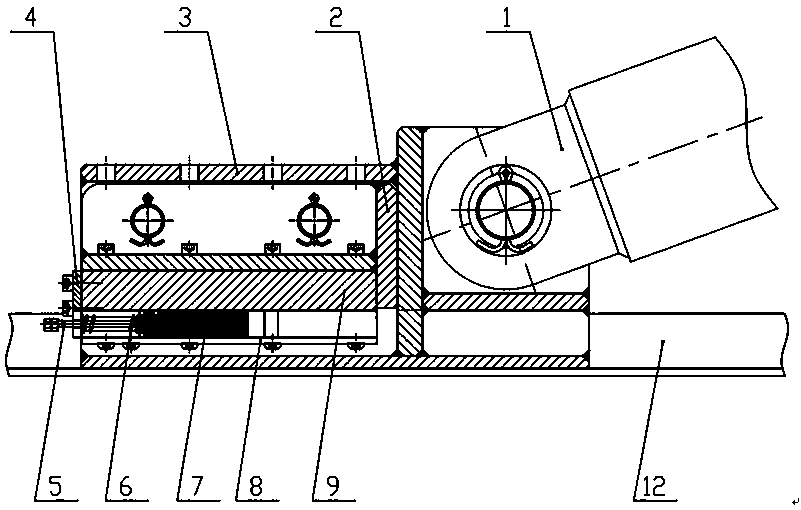
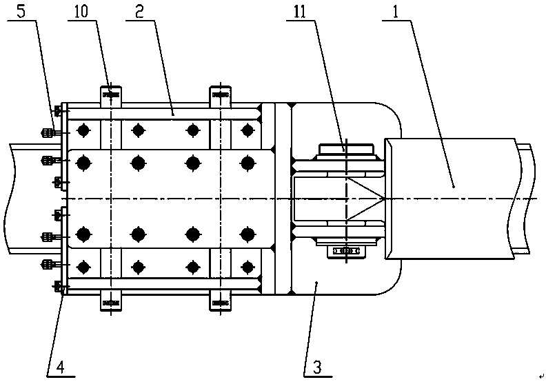
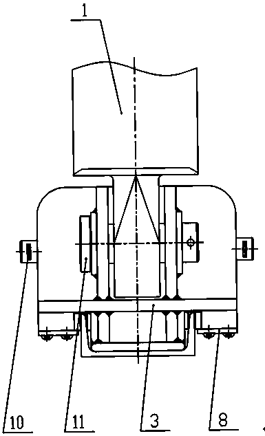
[0027] like figure 1 — image 3 As shown, the device consists of a push cylinder 1, a reaction frame 2, a push seat 3, a tail seal plate 4, a fixing bolt 5, a compression spring 6, a wedge block 7, a wedge support plate 8, a wedge seat 9, Long pin 10, bearing pin 11 and channel steel track 12 form.

[0028] Among them, a reaction force frame 2 is respectively placed on both sides of the push seat 3, and is connected with the reaction force frame 2 by two long pins 10; The wedge block 7 is embedded in the dovetail groove at the bottom of the wedge block seat 9; the friction surface of the wedge block 7 is designed to be serrated and can slide along the edge of the dovetail groove; the fixing bolt 5 passes through the tail sealing plate 4 and the wedge block 7 Carry out fastening connection, be provided with stage clip 6 between the two; Wedge supporting plate 8 and the bottom end of wedge seat 9 carry out fastening connection by hexagon socket head cap screw, be used to suppo...


PUM


Abstract

The invention relates to a self-adaptive steel channel rail clamping device. The self-adaptive steel channel rail clamping device comprises a pushing oil cylinder, counter-force frames, a pushing seat, tail seal plates, fixed bolts, compressed springs, wedge-shaped blocks, wedge block support plates, wedge block seats, a long pin and a hinge pin. The two sides of the pushing seat are each connected with one counter-force frame. The counter-force frames are each connected with one wedge block seat. The wedge-shaped blocks are embedded into dovetail grooves in the bottom ends of the wedge block seats. The fixed bolts penetrate through tail seams to be connected with the wedge-shaped blocks. The compressed springs are arranged between the fixed bolts and the wedge-shaped blocks. The wedge block support plates are connected with the bottom ends of the wedge block seats to be used for supporting the wedge-shaped blocks. The tail seal plates are connected with the tails of the wedge block seats to seal the dovetail grooves. A piston rod of the pushing oil cylinder is connected with the pushing seat. The self-adaptive steel channel rail clamping device has the characteristics of being low in system cost, good in moving stability, high in automation degree, simple to operate, good in clamping effect and the like.

Description

technical field [0001] The invention belongs to the technical field of rail clamping devices for hydraulic jacking and sliding construction, in particular to a rail clamping device, in particular to a self-locking channel steel rail clamping device. Background technique [0002] At present, with the rapid growth of my country's economy and the vigorous development of infrastructure construction, construction projects of large-space and long-span structures are increasing, and the installation of some large components puts forward higher requirements for construction technology. In the face of large grid and truss structures, the traditional high-altitude hoisting technology not only has a large construction area, high construction costs, and a long construction period, but also cannot meet the requirements of installation accuracy. Therefore, the construction technology of block assembly and cumulative slippage is gradually being promoted and used. [0003] Hydraulic jackin...

Claims


Application Information

Patent Timeline
Patent Type & Authority Patents(China)
IPC IPC(8): E04G21/16B66C9/18E04B1/35
CPCB66C9/18E04B1/35E04B2001/3588E04G21/16
Inventor 卞永明杨濛刘广军李安虎
Owner TONGJI UNIV
Features
  • R&D
  • Intellectual Property
  • Life Sciences
  • Materials
  • Tech Scout
  • Unparalleled Data Quality
  • Higher Quality Content
  • 60% Fewer Hallucinations
Learn More