
Binding equipment

A device and wire technology, applied in the field of wire binding equipment, can solve the problems of time-consuming and labor-intensive, and achieve the effect of solving time-consuming and labor-intensive problems.

Active Publication Date: 2018-11-09
GREE ELECTRIC APPLIANCES INC
View PDF5 Cites 0 Cited by
  • Summary
  • Abstract
  • Description
  • Claims
  • Application Information

AI Technical Summary

Problems solved by technology

[0003] The main purpose of the present invention is to provide a wire binding device to solve the time-consuming and labor-intensive problem in the prior art when manually using cable ties for binding

Method used


Image

  • Binding equipment
  • Binding equipment

Examples


Embodiment Construction

[0028] It should be noted that, in the case of no conflict, the embodiments of the present invention and the features in the embodiments can be combined with each other. The present invention will be described in detail below with reference to the accompanying drawings and examples.

[0029] In order to enable those skilled in the art to better understand the solutions of the present invention, the following will clearly and completely describe the technical solutions in the embodiments of the present invention in conjunction with the drawings in the embodiments of the present invention. Obviously, the described embodiments are only It is an embodiment of a part of the present invention, but not all embodiments. Based on the embodiments of the present invention, all other embodiments obtained by persons of ordinary skill in the art without creative efforts shall fall within the protection scope of the present invention.

[0030] It should be noted that the terms "first" and "...


PUM


Abstract

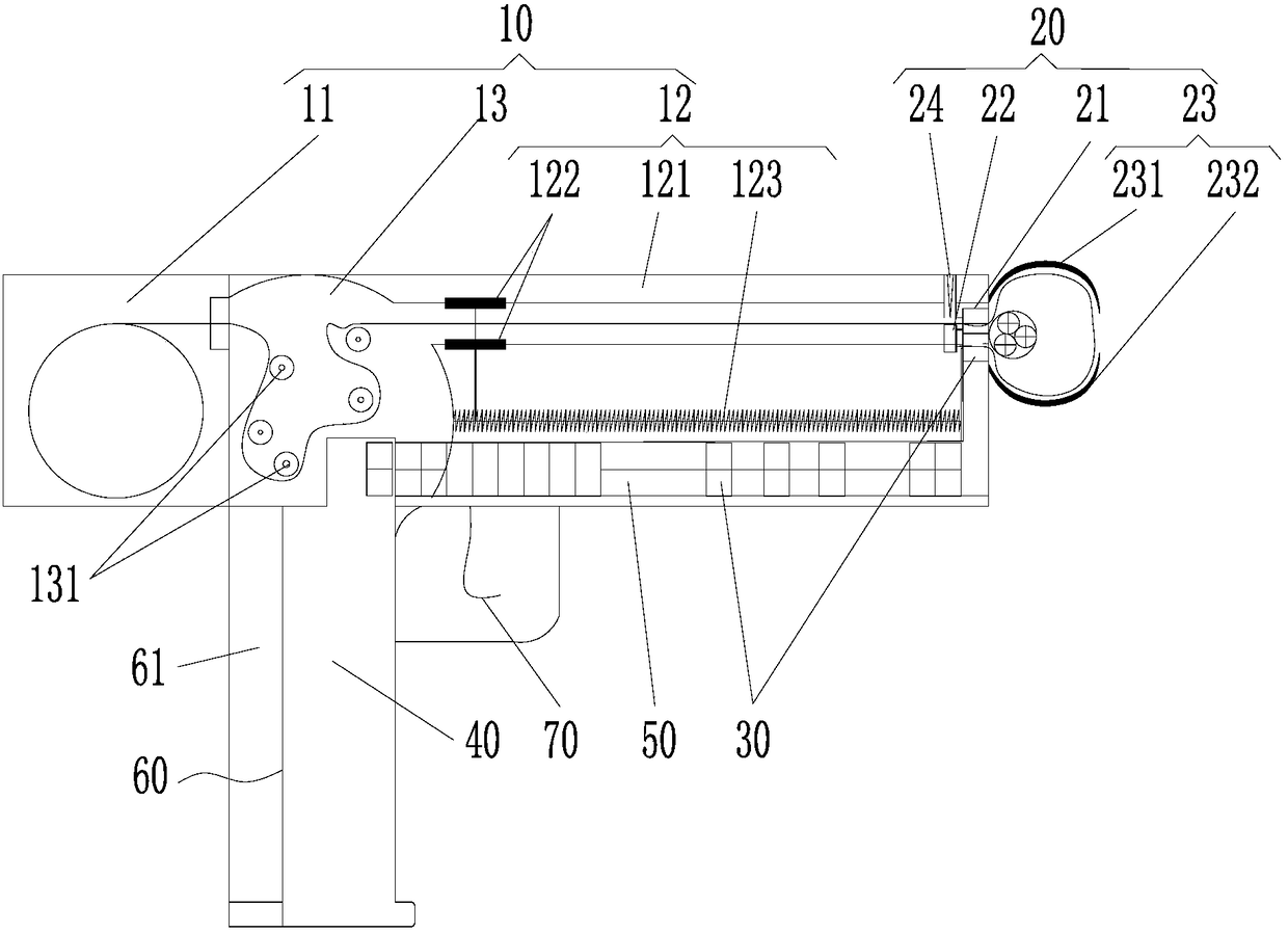
The invention provides wire binding equipment. The wire binding equipment comprises a binding belt supply mechanism, and a binding belt binding mechanism connected with the binding belt supply mechanism. The binding belt supply mechanism is used for supplying binding belts; and the binding belt binding mechanism is used for receiving the binding belts and fixing the binding belts on a binding head to bind pieces to be bound. When the pieces to be bound are bound, the binding belt supply mechanism provides the binding belts; and the binding belt binding mechanism winds the binding belts on the pieces to be bound, and fixes the binding belts on the binding head to tighten the binding belts so as to achieve the binding purpose. The wire binding equipment uses the binding belt supply mechanism and the binding belt binding mechanism for replacing manual hand holding and traction of the binding belts to firmly bind the pieces to be bound, and solves the problems of time and labor wastes in manual traction of the binding belts and possible hand scratch in the traction process.

Description

technical field [0001] The invention relates to the technical field of assembly tooling, in particular to a wire binding device. Background technique [0002] At present, when using cable ties to bundle the wire harness. Usually, workers hold cable ties to carry out the thread binding work. This process is very complicated, time-consuming and labor-intensive. Contents of the invention [0003] The main purpose of the present invention is to provide a wire binding device to solve the time-consuming and labor-intensive problem in the prior art when manually using cable ties for binding. [0004] In order to achieve the above object, according to one aspect of the present invention, a wire binding device is provided, including a cable tie supply mechanism and a cable tie binding mechanism connected with the cable tie supply mechanism. Wherein, the cable tie supply mechanism is used to supply the cable tie, and the cable tie binding mechanism is used to receive the cable tie...

Claims


Application Information

Patent Timeline
Patent Type & Authority Patents(China)
IPC IPC(8): B65B13/08B65B13/22B65B13/26
CPCB65B13/08B65B13/22B65B13/26
Inventor 张帅王奇关德灿吴扬军董柏林欧阳虎欧活军
Owner GREE ELECTRIC APPLIANCES INC
Learn More