An energy-saving section steel automatic packing device and process

An energy-saving, section steel technology, applied in the direction of packaging, strapping materials, strapping machine parts, etc., can solve the problems of increasing the cost of use, increasing the cost and burden of pollution control, etc., to achieve fast strapping, neat and beautiful stacking, and less The effect of small production costs

Active Publication Date: 2020-06-30
HUATIAN NANJING ENG & TECH CORP MCC
View PDF4 Cites 0 Cited by
  • Summary
  • Abstract
  • Description
  • Claims
  • Application Information

AI Technical Summary

Problems solved by technology

According to a preliminary estimate, it costs about 1.38 yuan for packing materials per ton of steel for bars and profiles. For a production line of bars and profiles with an annual output of 1 million tons, it needs to invest 1.38 million yuan, which invisibly increases the cost of manufacturers and users. Another problem is derived from this: so many packaged materials are produced, after the whole process of burning-iron-steel-rolling, and later used as waste to re-steel-smelting and other production processes, the waste gas emissions caused by the production process directly increase. Therefore, there is an urgent need for a recyclable and reusable clamp-type packaging material, which can save energy, improve the environment, and reduce the cost per ton of steel

Method used


Image

  • An energy-saving section steel automatic packing device and process
  • An energy-saving section steel automatic packing device and process
  • An energy-saving section steel automatic packing device and process

Examples


Embodiment 1

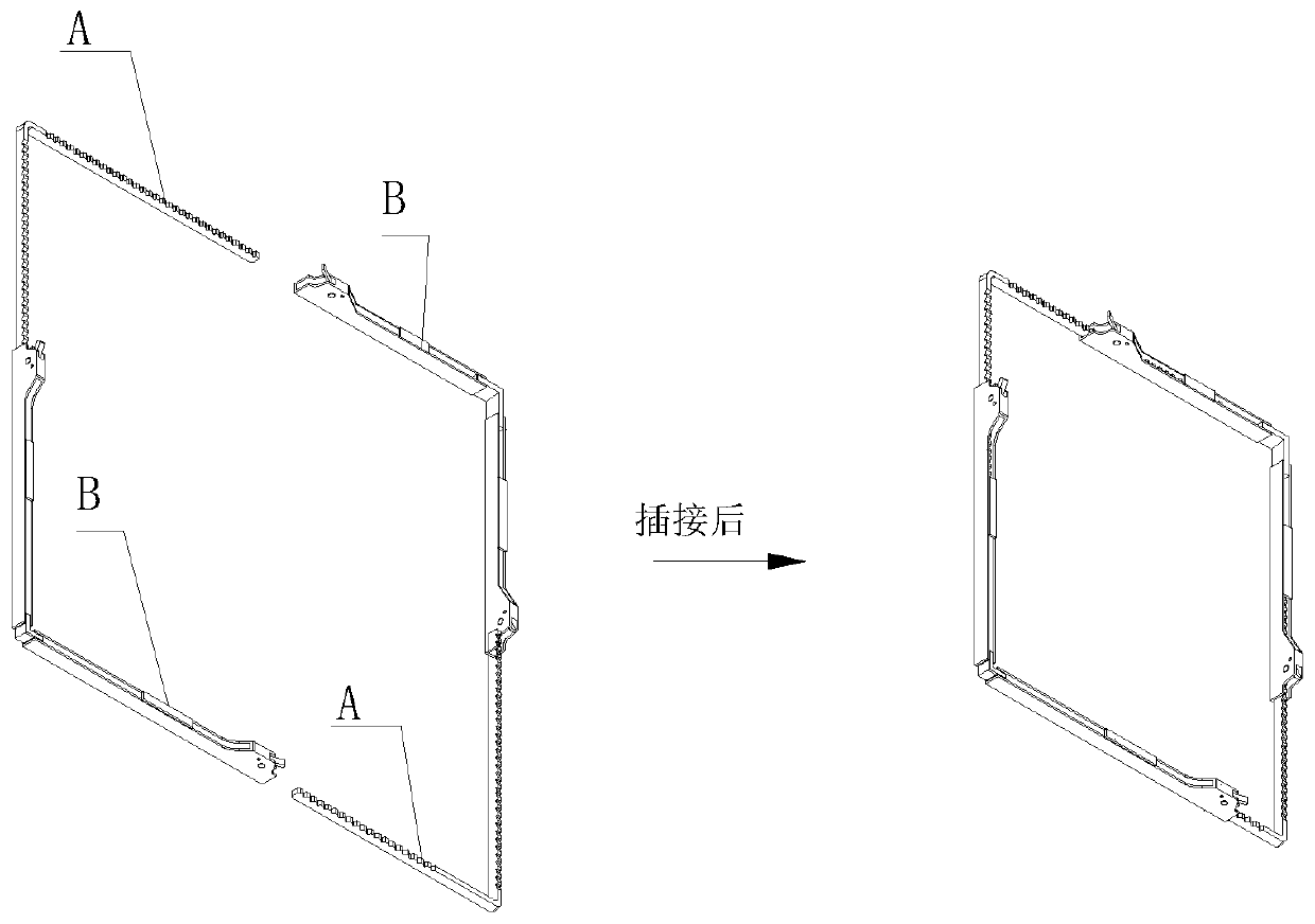
[0040] See Figure 1~ Figure 7 , what this embodiment provides is an energy-saving section steel automatic binding device, which uses a clamp as a binding piece for binding section steel stacking, see Figure 1-2 , there are two identical racks A and racks B staggered to form a mouth-shaped collar. Since the pawls set by the racks and the ratchets of the racks form anti-reverse sliding, so by pushing the racks or racks You can shrink the collar to complete the bundled pallet, and keep it tight.

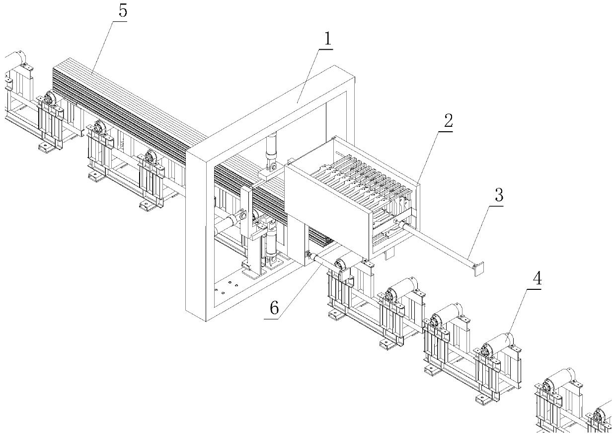
[0041] As shown in Figure 1, the device includes a mouth-shaped support 1, a jig delivery box 2 for transporting jigs, a jig delivery rod 3 for pushing the jig into the station, a delivery roller 4 for transporting pallets, and a jig delivery box driving cylinder 6 ;

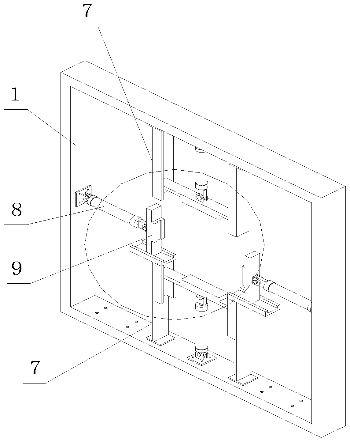
[0042] See figure 2 , image 3 , four jacking cylinders 8 are arranged axially in the mouth-shaped support 1, and a jacking bracket 7 is arranged; the end of the jacking cylinder 8 is provided with a jacking block ...

Embodiment 2

[0047] See Figure 6 , what this embodiment provides is an energy-saving section steel automatic binding device, and the difference from Embodiment 1 is that the mouth-shaped support 1 is replaced with a door-shaped frame 18, and the clamp push plate 14 is not provided, and two clamp conveying rods pass through instead. The push block pushes the clamp.

Embodiment 3

[0049] Provide a kind of section steel automatic binding process using the above-mentioned device, comprising Figure 9 Steps shown:

[0050] Step 1. Move the jig transport box to the top of the push bracket, push the jig through the conveying mechanism, and make the jig fall onto the push bracket along the limit groove;

[0051] Step 2, the stacked section steel enters the binding station through the conveying roller, so that the stacked section steel is stacked into the clamp collar;

[0052] Step 3, the push mechanism on the strapping frame pushes the fixture to shrink the collar of the fixture until the fixture fits on the stacking surface of the section steel;

[0053] Step 4, drive the conveying roller to make the pallet that has been bundled at one end pass through the strapping frame, and make the other end go over the strapping frame,

[0054] Step 5, move the jig transport box to the top of the push bracket, push the jig through the conveying mechanism, and make the ...


PUM


Abstract

The invention provides an energy-saving and automatic profile steel packaging device. The device comprises a binding frame, a stacked-profile-steel conveying device, a clamp conveying device and a pushing device and is characterized in that the pushing device comprises a plurality of pushing rods and pushing blocks, the pushing rods are circumferentially arranged in the binding frame and located on the same vertical plane, the pushing blocks are arranged at the ends of the pushing rods, and the pushing direction of the pushing rod face the center of the binding frame; the bottom of the bindingframe is provided with a support platform for placing clamps; the stacked-profile-steel conveying device comprises conveying rollers passing the binding frame and a stacked-profile-steel conveying rack, the conveying rollers are vertical to the binding frame and penetrate the frame the clamp conveying device is arranged on one side of the vertical plane and comprises a clamp conveying box, a clamp conveying mechanism and a clamp box pushing mechanism, the clamp conveying box is located above the conveying rollers, and the bottom of the clamp conveying box is provided with a clamp conveying port. The energy-saving and automatic profile steel packaging device has the advantages that stacked profile steel can be continuously automatically bound, the stacked profile steel is neat and attractive, and high work efficiency is achieved.

Description

[0001] Field [0002] The invention relates to the field of metallurgical production, in particular to an energy-saving section steel automatic packing device and process. [0003] technical background [0004] At present, the technology of automatic packing machine for rods and profiles at home and abroad is quite mature. The methods used are high-wire or steel belt packing, and the packing materials are all for one-time use. The used packing materials can only be sold as scrap steel to steel mills for recycling. Melting steel. According to a preliminary estimate, it costs about 1.38 yuan to pack a ton of steel for bars and profiles. For a bar and profile production line with an annual output of 1 million tons, it needs to invest 1.38 million yuan, which invisibly increases the cost of manufacturers and users. Another problem is derived from this: so many packaged materials are produced, after the whole process of burning-iron-steel-rolling, and later used as waste to re-stee...

Claims


Application Information

Patent Timeline
Patent Type & Authority Patents(China)
IPC IPC(8): B65B13/02B65B13/18B65B35/42
CPCB65B13/02B65B13/18B65B35/42
Inventor 沐贤春刘刚石海军方实年徐勇何家宝
Owner HUATIAN NANJING ENG & TECH CORP MCC
Why Eureka
Try Eureka