A cavity air inlet flow velocity adjusting device

A flow rate adjustment and cavity technology, applied in valve devices, valve operation/release devices, valve details, etc., can solve problems such as affecting equipment production capacity and difficult to control air intake flow rate, so as to improve equipment production capacity and easy intake air volume. Control, smooth change effect

Inactive Publication Date: 2017-05-03
PIOTECH CO LTD
View PDF0 Cites 2 Cited by
  • Summary
  • Abstract
  • Description
  • Claims
  • Application Information

AI Technical Summary

Problems solved by technology

[0003] The purpose of the present invention is to solve the above problems, and mainly solve the technical problems existing in the prior art that the intake air flow rate is difficul

Method used


Image

  • A cavity air inlet flow velocity adjusting device
  • A cavity air inlet flow velocity adjusting device

Examples


Embodiment

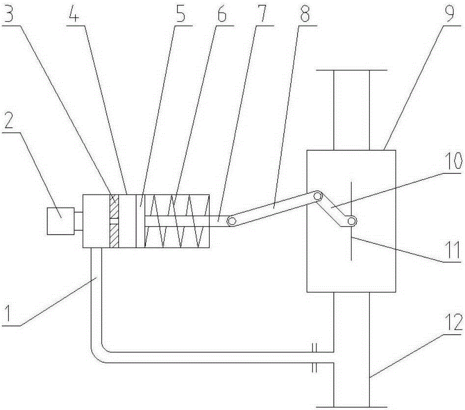
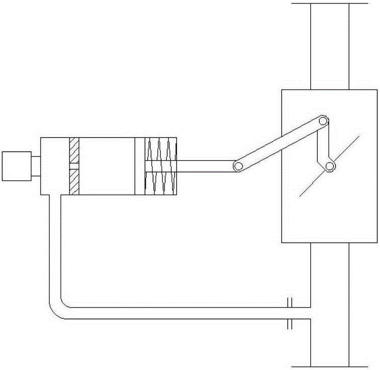
[0011] refer to figure 1 and figure 2 , a cavity intake flow rate regulator, including a cylinder intake pipe 1, a pressure regulating valve 2, a small hole baffle 3, a cylinder 4, a piston 5, a spring 6, a piston rod 7, a connecting rod 8, a valve body 9, a valve Sheet rod 10, valve sheet 11, intake pipe 12. The valve plate 11 is installed in the valve body 9 and can rotate around the pin on the valve body 9 in the valve body; the valve plate 11 is connected and fixed with the valve plate rod 10 . Described air intake pipe 12 is connected with valve body 9 intake ends; Cylinder air intake pipe 1 two ends are respectively connected with air intake pipe 12 and cylinder 4, and cylinder 4 is provided with piston 5, and piston 5 is connected with piston rod 7 and is fixed. Described spring 6 is positioned in cylinder 4, and one end is in contact with piston 5, and the other end is in contact with cylinder 4 inner end face, and the elastic force of spring 6 can act on piston 5, ...


PUM


Abstract

The invention relates to an air inlet flow velocity adjusting device, in particular to an adjusting device which can change air inlet velocity with the change of cavity air inlet flow in the manufacture of semiconductors. The device can adjust air inlet flow velocity and enables air inlet velocity to decrease along with the increase of air flow quantity. The device comprises an air cylinder air inlet pipe, a pressure adjusting valve, a small hole blocking sheet, an air cylinder, a piston, a spring, a piston rod, a connecting rod, a valve body, a valve plate rod, a valve plate and an air inlet pipe, which form an air cylinder execution part and a valve body part. The increase of air inlet quantity can change the displacement of the piston; the piston rod can make the valve plate rotate via the connecting rod and the valve plate rod, and the rotation of the valve plate can adjust the flow velocity of air inlet. When air in a cavity is discharged or extracted out and the air pressure in the cavity becomes stable, the piston and the valve plate can return to the initial positions. The device enables the change of cavity air inlet velocity to be gentle, enables air inlet quantity to be easily controlled, shortens the time of an air inlet process and increases the capacity of apparatuses.

Description

technical field [0001] The invention relates to an adjusting device for the air intake flow rate of a cavity, in particular to an adjusting device which can change the intake air velocity with the change of the intake air flow rate of the cavity in semiconductor manufacturing. The invention belongs to the application technical field of semiconductor thin film equipment. Background technique [0002] Airtight cavities in semiconductor manufacturing require air intake and exhaust. The intake time must meet certain requirements, and the intake volume requirement is easy to control. When the intake air is taken in at a constant and large intake speed, the difficulty of controlling the intake air volume increases. When the intake velocity is low and the intake velocity remains constant, the intake time will be longer, which will affect the equipment capacity. Contents of the invention [0003] The purpose of the present invention is to solve the above problems, and mainly so...

Claims


Application Information

Patent Timeline
IPC IPC(8): F16K17/20F16K31/363H01L21/67
CPCF16K17/20F16K31/1221F16K31/363H01L21/67017
Inventor 门恩国
Owner PIOTECH CO LTD
Why Eureka
Try Eureka