Method of pre-determining footprint position of satellite laser altimeter

A technology of laser altimeter and footprints, which is applied to measuring devices, instruments, radio wave measuring systems, etc., to achieve the effects of saving test expenses, high forecasting accuracy, and reducing manpower and material resources

Active Publication Date: 2017-05-10
自然资源部国土卫星遥感应用中心
View PDF4 Cites 9 Cited by
  • Summary
  • Abstract
  • Description
  • Claims
  • Application Information

AI Technical Summary

Problems solved by technology

Since there are no surveying and mapping satellites in orbit in the world that in

Method used


Image

  • Method of pre-determining footprint position of satellite laser altimeter
  • Method of pre-determining footprint position of satellite laser altimeter
  • Method of pre-determining footprint position of satellite laser altimeter

Examples


Embodiment Construction

[0023] The invention will be described more fully below with reference to the accompanying drawings, which illustrate exemplary

[0024] Example.

[0025] According to the embodiments of the present invention, the space-borne laser altimeter can be randomly selected to construct the footprint position prediction model; preferably, the implementation case of the present invention is based on the footprint position prediction model of the laser altimeter of No. 3, 02 star Build as an example, but not limited to.

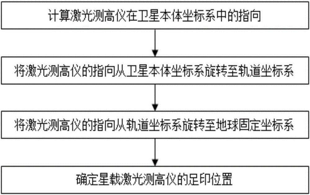
[0026] Such as figure 1 As shown, the construction of the laser altimeter prediction model and the construction of the optically rigorous geometric imaging model have the same process, which involves the rotation between each coordinate system, and finally transmits the pointing on the star to the ground point through the rotation of each coordinate system. The space-borne laser altimeter footprint position prediction model construction method proposed by the present...


PUM


Abstract

The invention discloses a method of pre-determining footprint position of a satellite laser altimeter. In the method, a traditional optical camera imaging principle is applied and altitude measurement mechanism of the laser altimeter is fully considered. A footprint position determination result satisfies actual flight transit situation of a satellite well. The method is high in calculation precision, reduces unnecessary labor intensity and resource consumption as most as possible, and saves a large amount of test cost.

Description

technical field [0001] The invention relates to the field of on-orbit geometric calibration of space-borne laser altimeters, in particular to a method for predetermining the footprint position of space-borne laser altimeters, which is applied in the process of on-orbit geometric calibration of space-borne laser altimeters Prediction of the deployment position of the laser ground detector. Background technique [0002] The successful implementation of the on-orbit geometric calibration test is one of the necessary conditions for the spaceborne laser altimeter to obtain high-precision altimetry data. The prediction of the footprint position of the spaceborne laser altimeter is the first step in the on-orbit geometric calibration, and it is also a very critical step. The accuracy of the forecast is not only related to the difficulty of the field layout of the entire calibration test, but even determines the success or failure of the test. [0003] At present, only ICESat-GLAS...

Claims


Application Information

Patent Timeline
IPC IPC(8): G01C25/00G01S7/497
CPCG01C25/00G01S7/497
Inventor 谢俊峰唐新明付兴科莫凡高小明李国元朱广彬张强窦显辉赵利平
Owner 自然资源部国土卫星遥感应用中心
Why Eureka
Try Eureka