
Display device

A display device and display panel technology, applied in the direction of instruments, optics, optical components, etc., can solve the problems of color shift, inconsistent image tilt direction, etc., and achieve the effect of improving the color shift problem

Active Publication Date: 2017-05-24
BOE TECH GRP CO LTD +1
View PDF6 Cites 4 Cited by
  • Summary
  • Abstract
  • Description
  • Claims
  • Application Information

AI Technical Summary

Problems solved by technology

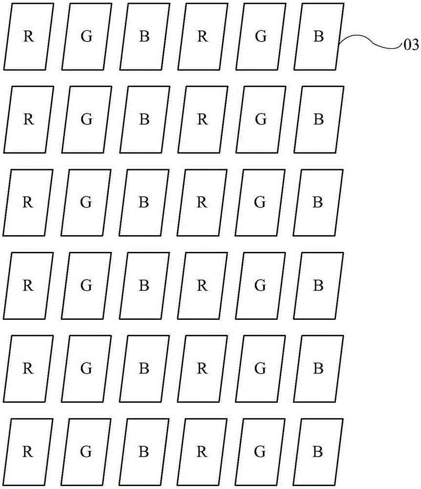
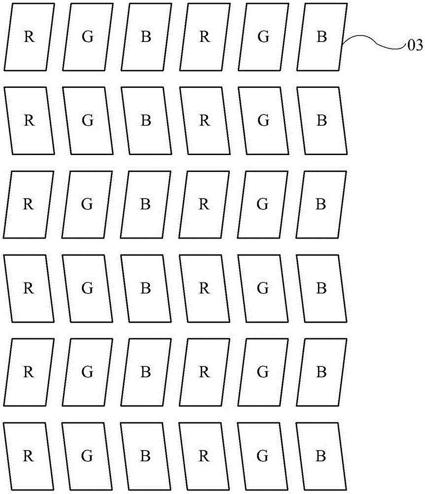
like figure 2 As shown, in the 2P2D pixel structure, the sub-pixels 03 in odd rows and even rows are inclined in opposite directions. When it is applied to 3D display, the left and right eyes respectively receive the light emitted by sub-pixels 03 in odd rows or even rows, resulting The tilt direction of the image seen by the left eye and the image seen by the right eye are inconsistent, resulting in color cast

Method used


Image

  • Display device
  • Display device
  • Display device

Examples


Embodiment Construction

[0030] The following will clearly and completely describe the technical solutions in the embodiments of the present invention with reference to the accompanying drawings in the embodiments of the present invention. Obviously, the described embodiments are only some, not all, embodiments of the present invention. Based on the embodiments of the present invention, all other embodiments obtained by persons of ordinary skill in the art without making creative efforts belong to the protection scope of the present invention.

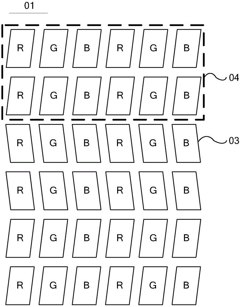
[0031] An embodiment of the present invention provides a display device, such as image 3 and Figure 4 As shown, a display panel 01 is included, and the display panel 01 includes multiple rows of sub-pixels 03, and each sub-pixel 03 is a parallelogram, and the first side of the parallelogram is parallel to the row direction, and the second side is arranged obliquely relative to the vertical direction, and the vertical The vertical direction is perpendicular ...


PUM


Abstract

The present invention provides a display device and belongs to the display technical field. With the display device of the invention adopted, the problem of color cast of 3D display can be solved. The display device comprises a display panel; the display panel comprises a plurality of rows of sub-pixels; each sub-pixel is in the shape of a parallelogram, the first side of the parallelogram being parallel to the direction of the rows, the second side of the parallelogram being inclined with respect to a vertical direction, the vertical direction being perpendicular to the direction of the rows; every two adjacent rows of sub-pixels constitute a pixel group, the inclination directions of the second sides of the sub-pixels in the pixel group being consistent, the inclination directions of the second sides of sub-pixels in an adjacent pixel group being opposite; the display device further comprises a grating device; and the grating device is used for respectively projecting an image displayed by the odd-numbered rows of sub-pixels of the display panel and an image displayed by the even-numbered rows of sub-pixels to a left eye and a right eye.

Description

technical field [0001] The present invention relates to the field of display technology, in particular to a display device. Background technique [0002] With the continuous development of display technology, 3D (3-Dimension, referred to as three-dimensional) display technology has attracted much attention. 3D display technology can make the picture three-dimensional and realistic. Realize 3D display effect. [0003] Usually, the grating is combined with a 2D (2-dimension, referred to as two-dimensional) display panel. In the 3D mode, the grating can control the light emitted by the pixel corresponding to the left eye to only enter the left eye, and control the light emitted by the pixel corresponding to the right eye. Light only enters the right eye. [0004] Currently, the pixel structure adopted by the 2D display panel is 1P (pixel, referred to as pixel) 1D (direction, referred to as direction) or 2P2D. Among them, such as figure 1 As shown, in the 1P1D pixel structur...

Claims


Application Information

Patent Timeline
IPC IPC(8): G02B27/22G02F1/1333
CPCG02B30/27G02F1/13338
Inventor 张勇王凯旋王世君薛艳娜包智颖肖文俊白璐米磊华刚
Owner BOE TECH GRP CO LTD
Learn More