Row driving circuit, display device and row driving method

A line driver and circuit technology, applied in static indicators, instruments, etc., can solve the problems of low pull-down maintenance, unstable circuit, and color shift of liquid crystal displays, so as to improve image quality, improve stability, and improve color shift problems. Effect

Inactive Publication Date: 2019-08-23
KUSN INFOVISION OPTOELECTRONICS
View PDF8 Cites 5 Cited by
  • Summary
  • Abstract
  • Description
  • Claims
  • Application Information

AI Technical Summary

Problems solved by technology

[0005] In the prior art, the pull-down sustaining level of the pull-down sustaining circuit for the output driving signal such as the gate scanning signal is very low, resulting in a certain degree of change in the output driving signal when the scanning circuit is turned off, which in turn causes the row driving circuit to fail when driving. The circuit is unstable due to the change of the driving signal, so that the liquid crystal display will have a problem of color shift under a large viewing angle, which will affect the display quality

Method used


Image

  • Row driving circuit, display device and row driving method
  • Row driving circuit, display device and row driving method
  • Row driving circuit, display device and row driving method

Examples


Embodiment Construction

[0025] In order to facilitate the understanding of the present invention, the present invention will be described more fully below with reference to the associated drawings. Preferred embodiments of the invention are shown in the accompanying drawings. However, the present invention can be implemented in different forms and is not limited to the embodiments described herein. On the contrary, these embodiments are provided to make the understanding of the disclosure of the present invention more thorough and comprehensive.

[0026] Unless otherwise defined, all technical and scientific terms used herein have the same meaning as commonly understood by one of ordinary skill in the technical field of the invention. The terms used herein in the description of the present invention are for the purpose of describing specific embodiments only, and are not intended to limit the present invention.

[0027] Hereinafter, the present invention will be described in detail with reference t...


PUM


Abstract

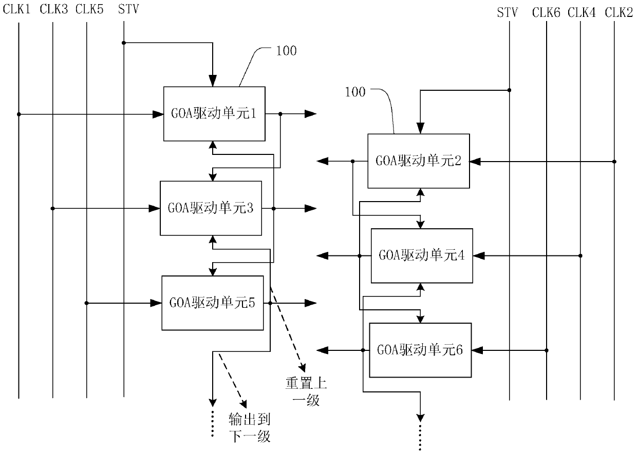
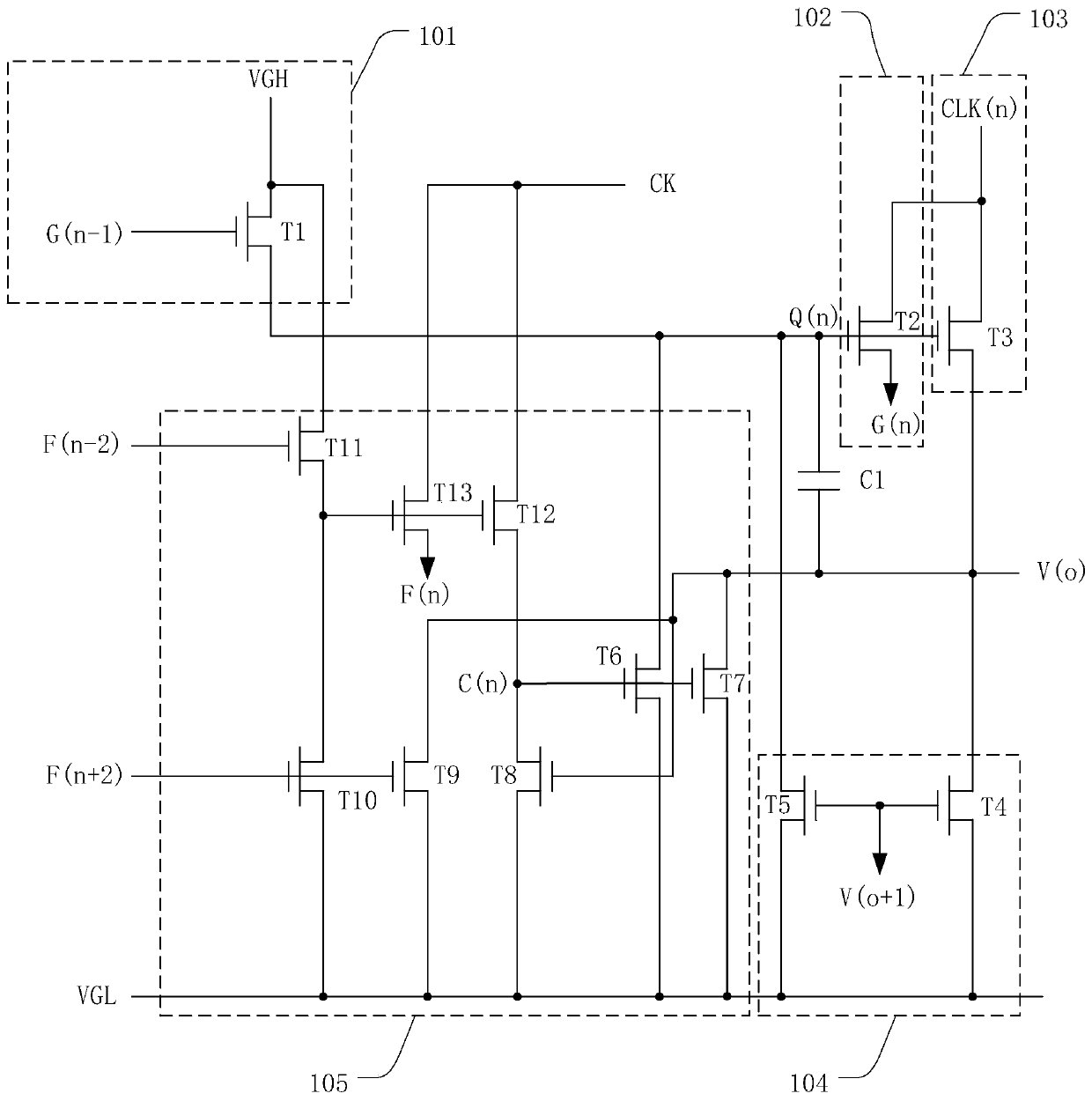
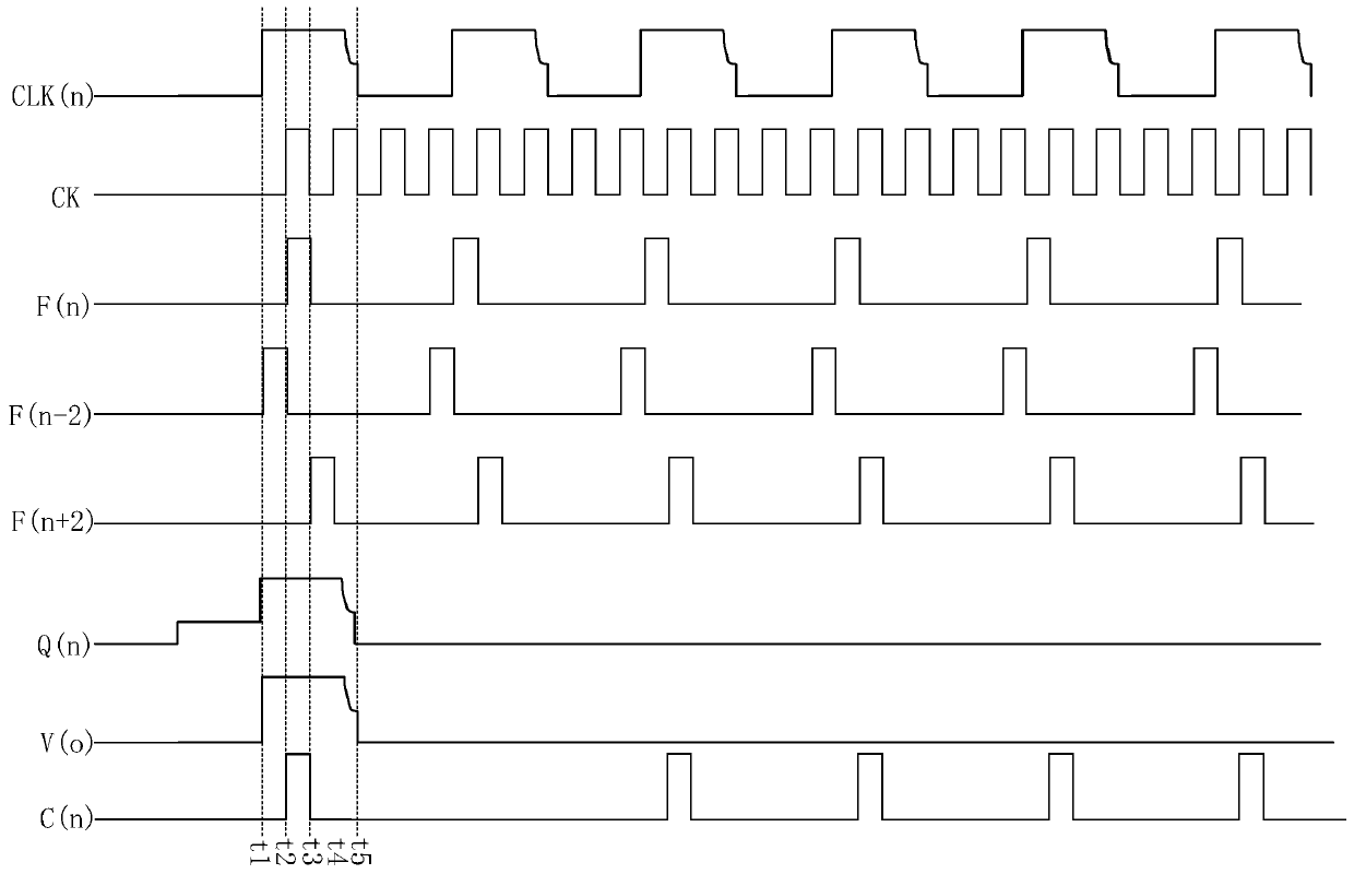
The invention discloses a row driving circuit which comprises a plurality of cascaded driving units, and each driving unit comprises a pull-up control module, a pull-up module, a download module, a pull-down module, a pull-down maintaining module and a bootstrap capacitor. The pull-up module, the pull-down maintaining module, the pull-down maintaining module and the bootstrap capacitor are respectively connected with a first potential point and the scanning signal output end of the grid line of the level. The pull-up control module and the download circuit are respectively connected with the first potential point; wherein the pull-down maintaining module is used for receiving the second clock signal so as to maintain the potential signal of the first potential point and the grid line scanning signal of the stage in a low potential state, and the frequency of the second clock signal is twice or more than twice of the frequency of the clock signal of the stage. The invention further discloses a display device and a row driving method. The influence of the signal-to-noise ratio on the circuit can be effectively reduced, and the stability of the circuit is improved.

Description

technical field [0001] The invention relates to the field of display technology, in particular to a row driving circuit, a display device and a row driving method. Background technique [0002] At present, the driving of the horizontal scanning lines of the active flat panel display panel is mainly completed by an IC external to the panel, and the external IC can control the step-by-step charging and discharging of the horizontal scanning lines connected to the pixels (pixels) of the panel. The GOA (Gate Driver Array, array substrate line drive) technology can use the original process of the display panel to manufacture the driving circuit of the horizontal scanning line on the substrate around the display area, so that it can replace the external IC to complete the driving of the horizontal scanning line. . GOA technology can simplify the manufacturing process of display panels, save the IC bonding process in the direction of horizontal scanning lines, have the opportunity...

Claims


Application Information

Patent Timeline
IPC IPC(8): G09G3/36
CPCG09G3/3677
Inventor 梁文龙
Owner KUSN INFOVISION OPTOELECTRONICS
Why Eureka
Try Eureka