Connector device with locking means and connector for use therein

A technology of connectors and components, which is applied in the direction of two-part connection device, parts of the connection device, connection, etc., can solve the problem of the device not having

Active Publication Date: 2017-05-24
HIROSE ELECTRIC GROUP
View PDF5 Cites 2 Cited by
  • Summary
  • Abstract
  • Description
  • Claims
  • Application Information

AI Technical Summary

Problems solved by technology

Existing devices do not have any functionality against this force

Method used


Image

  • Connector device with locking means and connector for use therein
  • Connector device with locking means and connector for use therein
  • Connector device with locking means and connector for use therein

Examples


Embodiment Construction

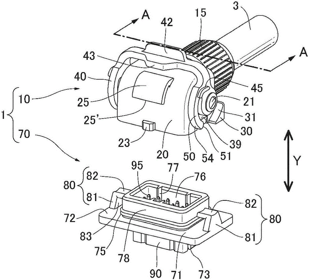
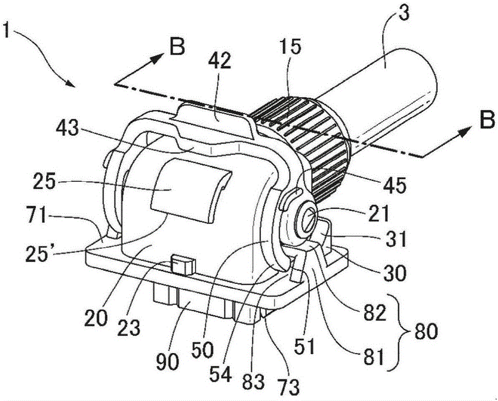
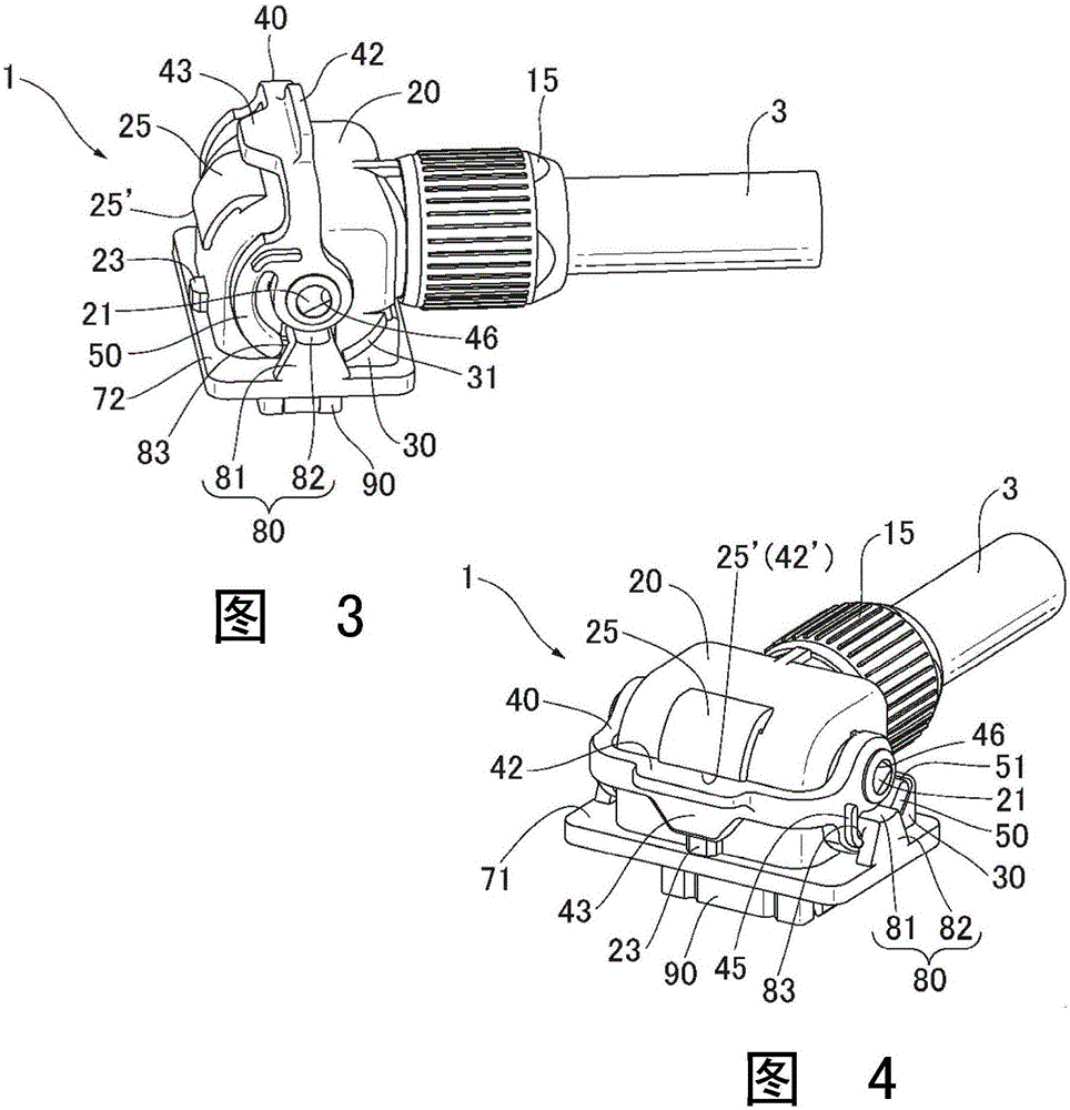
[0061] Hereinafter, a connector device according to a preferred embodiment of the present invention will be described with reference to the drawings. In addition, although the waterproof connector has been described as an example, the present invention can also be applied to various types of connector devices other than the waterproof connector.

[0062] figure 1 It is a perspective view showing the connector device 1 of the present invention. This connector device 1 is composed of a female connector 10 and a male connector 70 . The female connector 10 is connected to one end of the cable 3 for use, while the male connector 70 is used for being provided on the surface of a housing (not shown) of a device such as a motor. Both can fit each other by approaching in the fitting direction (arrow "Y" direction in the figure). figure 1 shows the state before the two are fitted, figure 2 , Fig. 3 shows the state after the two are fitted with the front perspective view and the s...


PUM


Abstract

Disclosed are a connector device with a locking means and a connector for use therein. The connector device is capable of maintaining the fitting state of a first connector and a second connector, by preventing a locking part from spreading to a second connector side thereby maintaining the locked state between a locking part and a locked part, even if a force is applied near the free end of an arm. A first housing of a first connector has a locking part having a free end, supported pivotally for the first housing. The locking part is locked by a locked part of the second housing of the second connector, after fitting the first and second connectors and then being rotated for the first housing. The first housing has a support for supporting the vicinity of the free end of the locked part locked thereby, on the side of the locking part opposite to the side facing the rotating shaft.

Description

[0001] This application is an invention submitted by the applicant on September 2, 2014 with the application number "201410442982.X" and the title of the invention is "connector device with locking element and connector for the connector device" A divisional application of a patent application. technical field [0002] The present invention relates to a connector device having a locking element, and more specifically, to a connector device having a locking element for maintaining a fitting state between connectors, and a connector used in the connector device. Background technique [0003] Patent Document 1 discloses an example of a conventional connector device having the above configuration. A side view of the disclosed connector device 100 is shown as Figure 9 shown. The connector device 100 is composed of a female connector 110 and a male connector 120 that can be fitted to each other. When the female connector 110 is mated with the male connector 120 , the fitted por...

Claims


Application Information

Patent Timeline
Patent Type & Authority Applications(China)
IPC IPC(8): H01R13/52H01R24/00H01R13/629H01R13/639
CPCH01R13/639
Inventor 长沼健一
Owner HIROSE ELECTRIC GROUP
Why Eureka
Try Eureka