Chain tensioner

A technology of tensioner and locking part, applied in the direction of belt/chain/gear, mechanical equipment, transmission device, etc., can solve problems such as chain tensioner failure, engine failure, etc., and achieve the effect of preventing non-action

Pending Publication Date: 2021-07-23
DAIDO KOGYO CO LTD
View PDF6 Cites 0 Cited by
  • Summary
  • Abstract
  • Description
  • Claims
  • Application Information

AI Technical Summary

Problems solved by technology

In the worst case, there is the possibility of forgetting to pull out the stop pin and causing the chain tensioner to fail, or the stop pin falling into the engine and causing engine failure

Method used


Image

  • Chain tensioner
  • Chain tensioner
  • Chain tensioner

Examples


Embodiment Construction

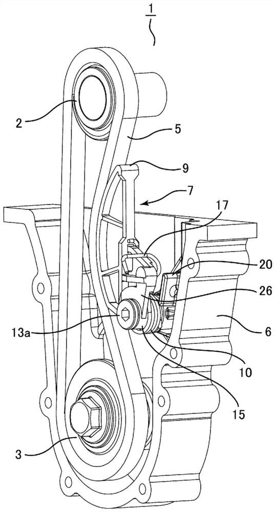
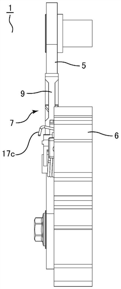
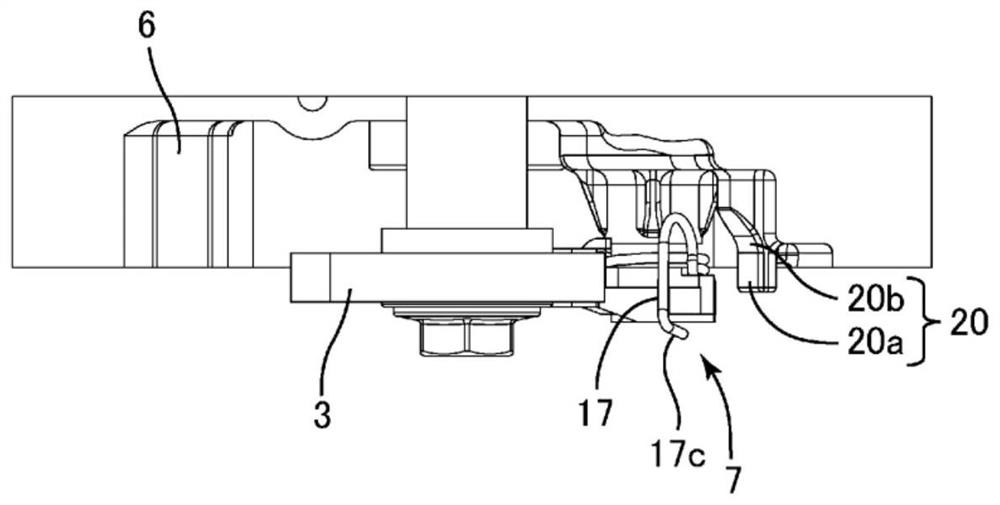
[0062] Embodiments of the present invention will be described below with reference to the drawings. Such as Figure 1 ~ Figure 2B As shown, the chain transmission device 1 of this embodiment has a driving side sprocket 2 linked with the engine crankshaft, a driven side sprocket 3 linked with auxiliary machines such as an oil pump and a balancer, and a sprocket 3 wound around these two chains. Chain 5 for wheels 2,3. The chain 5 is usually a roller chain, but may be other chains such as a silent chain. The chain transmission 1 is accommodated in a chain case 6 constituted by an engine block, and a chain tensioner 7 is arranged in the chain case 6 .

[0063] Such as Figure 3A ~ Figure 3D As shown, the chain tensioner 7 has a rod (arm) 9 that is in sliding contact with the slack side of the chain 5, and a twisted screw that is compressed between the rod and the chain case 6 and acts a predetermined force on the rod 9. spring 10. also, Figure 1 ~ Figure 3D The state shown ...


PUM


Abstract

The invention relates to a chain tensioner. A securing-side support arm (17) of a torsion coil spring (10) is provided with a locking part (17a) and a pressing part (17c). The locking part (17a) is accommodated in a recessed spring accommodation part (22) provided in a lever (9), and an engaging part (22a) makes contact with the locking part (17a), locking the biasing force of the spring. A pressing force (F) acts on the pressing part (17c), removing the locking part (17a) from the spring accommodation part (22) and releasing the locking caused by the engaging part (22a).

Description

technical field [0001] The present invention relates to a tensioner for applying tension to a chain. Specifically, it relates to a tensioner for a chain in which a torsional force for tension is applied to a tension rod using a torsion coil spring. Background technique [0002] Generally, a chain tensioner is used in a chain transmission for driving an auxiliary machine of an automobile engine such as an oil pump and a balancer to remove slack in the chain and prevent vibration of the chain during running. This tensioner includes a rod that abuts on the chain, and a torsion coil spring that acts on the rod as a force for chain tension. When attaching the chain tensioner to the chain, the torsion coil spring needs to be twisted and compressed If it is assembled in an unreasonable state, the installation work is troublesome. In addition, if it is assembled in an unreasonable state, the chain tensioner or the engine block may be damaged. [0003] Conventionally, a chain tensio...

Claims


Application Information

Patent Timeline
Patent Type & Authority Applications(China)
IPC IPC(8): F16H7/08
CPCF16H2007/081F16H2007/0872F16H2007/0893F16H2007/0897F16H7/08F16H2007/0842
Inventor 关秀明田中康太奥浩章
Owner DAIDO KOGYO CO LTD
Why Eureka
Try Eureka