An acoustic emission monitoring system

A monitoring system, acoustic emission technology, applied in measuring devices, using ultrasonic/sonic/infrasonic waves, instruments, etc., can solve the problems of acoustic emission detection limitations, prolonging the project progress, long cycle, etc., to achieve repeated use and ensure the coupling effect , enhanced stability and the effect of

Active Publication Date: 2019-07-30
SICHUAN UNIV
View PDF12 Cites 0 Cited by
  • Summary
  • Abstract
  • Description
  • Claims
  • Application Information

AI Technical Summary

Problems solved by technology

[0005] (1) At the engineering site, the acoustic emission probe is directly placed in the borehole, relying on the residual liquid medium (such as water) in the borehole as the medium for signal transmission between the rock mass and the acoustic emission probe, the acoustic emission probe will receive The detection signal is transmitted to the ground monitoring system through cables; however, this method has the following disadvantages: ① This implementation is only suitable for drilling holes with a downward direction, and for drilling holes that are completely horizontal or upward at a certain angle, it is difficult to store Even for the downward drilling, the rock mass around the drilling still needs to be relatively intact, so as to avoid the loss or seepage of the transmission medium from the borehole cracks, and ensure that the AE probe is always in the transmission medium, but the actual site However, it is difficult to meet this requirement, which affects the monitoring effect; ②Although the liquid between the rock mass and the acoustic emission probe can be used as the coupling medium for signal transmission, the density of the liquid is generally relatively low, and its signal transmission effect is not as good as that of the acoustic emission probe directly. The detection signal received by the transmitter probe in effective contact with the rock wall
[0006] (2) In order to ensure effective coupling between the acoustic emission probe placed in the borehole and the borehole wall, cement can also be poured into the borehole at the engineering site so that the acoustic emission probe and the rock wall are poured as a whole. Although this method It can solve the problem of effective transmission of detection signals, but there are still the following defects: ①The acoustic emission probe after casting is not recyclable, resulting in high monitoring costs; adjustment, only to re-drill and install new acoustic emission probes, which not only leads to high monitoring costs, but also leads to prolongation of the project progress and even delays in the construction period; The grouting effect of the installation part of the acoustic emission probe is difficult to guarantee, and there may be situations where the installation part of the acoustic emission probe cannot be effectively grouted, resulting in no effective coupling between the acoustic emission probe and the rock wall and no monitoring signal; Deeper, the greater the total shrinkage and deformation of the poured cement after solidification, the signal transmission cable of the acoustic emission probe bonded to the cement will bear tension due to the shrinkage and deformation of the cement, resulting in ineffective signal transmission; ④ During the excavation process Explosive blasting may cause the grouting surface and the rock wall surface to relax, resulting in a decrease in the effectiveness of monitoring signal transmission; ⑤The inside of the borehole is usually relatively humid, and it takes a long period for the grout to solidify after pouring, which will prolong the construction period; and the installation The process is time-consuming and laborious, requiring a series of professional grouting equipment and grouting personnel, which further increases the cost of monitoring
[0007] (3) Another implementation method is to use a simple fixed installation device to fix the acoustic emission probe inside the device, and then use a rigid non-movable metal transmission rod to send the fixing device to the installation site, and use pressure to push the acoustic emission probe to the top of the device. After it comes out, it is in contact with the rock wall of the borehole to achieve fixation. Its advantage is that it realizes the contact between the acoustic emission probe and the rock wall in the case of non-grouting, but there are still the following disadvantages: The distance between the walls is very close, so the fixed installation device and the drilling hole must have a concentric structure, and the hole wall needs to be smooth, but these requirements are difficult to guarantee in actual construction; ② Due to the large size of the fixed installation device, it is only suitable for Large drilling holes lead to higher drilling costs; ③The entire transmission rod and installation device are inserted into the drilling hole through force and rigidity, which not only has high friction, it is easy to wear out the cable or the acoustic emission probe, and it is easy to It is stuck in the drill hole and cannot be sent to the place where it needs to be installed; ④ Since the fixed installation device is rigidly inserted into the drill hole through external force, the installation process is not only time-consuming and laborious, but also the work efficiency is extremely low; ⑤ Due to the The hole wall is a cylindrical surface, while the end face of the acoustic emission probe is a plane. How to ensure that the end face of the acoustic emission probe is effectively coupled with the borehole wall is also a difficult problem to be solved in practical applications
[0008] Based on the disadvantages and defects in the above-mentioned various implementation methods, the application and promotion of acoustic emission detection in the monitoring of rock (body) stability and rockburst dynamic disasters is limited to a certain extent.
[0009] Therefore, how to install the acoustic emission probe in the borehole conveniently and effectively, and how to effectively couple the installed acoustic emission probe with the hole wall is still a difficult point in field monitoring and research at present, and there is a lack of relevant testing methods and technical support

Method used


Image

  • An acoustic emission monitoring system
  • An acoustic emission monitoring system
  • An acoustic emission monitoring system

Examples


Embodiment 1

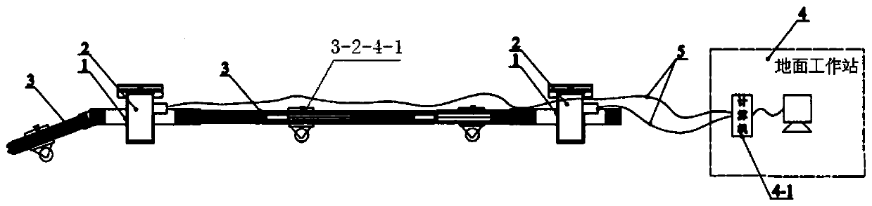
[0051] The acoustic emission monitoring system provided by this embodiment is as figure 1 As shown, it includes an acoustic emission sensor and a ground workstation 4, the acoustic emission sensor is used to be installed in the borehole 6 of the monitored rock mass 7, and the received monitoring signal is transmitted to the ground workstation 4 through a cable 5, and the ground workstation 4 The computer 4-1 processes and displays the monitoring signal from the emission sensor; the acoustic emission sensor is composed of the acoustic emission probe 2, the probe installation mechanism and the transmission mechanism 3 that transmits the installation mechanism equipped with the acoustic emission probe to the set position in the borehole Composition; there are two probe installation mechanisms 1 and two acoustic emission probes 2.

[0052] Such as Figure 9 , Figure 10 As shown, the above-mentioned acoustic emission probe 2 is a cylindrical structure with a cable connector 2-1 ...

Embodiment 2

[0066] The acoustic emission monitoring system provided by this embodiment, such as Figure 19 As shown, it includes an acoustic emission sensor and a ground workstation 4, the acoustic emission sensor is used to be installed in the borehole 6 of the monitored rock mass 7, and the received monitoring signal is transmitted to the ground workstation 4 through a cable 5, and the ground workstation 4 The computer 4-1 processes and displays the monitoring signal from the emission sensor; the acoustic emission sensor is composed of the acoustic emission probe 2, the probe installation mechanism and the transmission mechanism 3 that transmits the installation mechanism equipped with the acoustic emission probe to the set position in the borehole Composition; the number of the probe installation mechanism 1 and the acoustic emission probe 2 is three.

[0067] The structures of the probe installation mechanism 1 and the acoustic emission probe 2 provided in this embodiment are the same...


PUM


Abstract

The invention discloses an acoustic emission monitoring system comprising an acoustic emission sensor and a ground work station. The acoustic emission sensor is used for being mounted in a borehole of a monitored rock body and is composed of an acoustic emission probe, a probe mounting mechanism and a transmission mechanism for transmitting the mounting mechanism on which the acoustic emission probe is mounted to a preset position in the borehole. The probe mounting mechanism of the acoustic emission monitoring system of the invention solves the problem of effective installation and coupling of the acoustic emission sensor through the pluggable connection and cooperation between a second cover plate of a guide assembly and an upper end cap of a probe sleeve, not only facilitating acoustic emission probe transmission, but also ensuring the coupling effect between the acoustic emission probe and a borehole wall, thereby enhancing the monitoring and forecast reliability of the rock (body) engineering stability and rock burst dynamic disasters. In addition, the system can also achieve usage of multiple acoustic emission probes at the same time, with a wider range of applications.

Description

technical field [0001] The invention belongs to the technical field of rock (body) engineering safety monitoring in engineering construction, and relates to an acoustic emission monitoring system. Background technique [0002] Rock (body) deformation and damage during engineering construction, especially rockburst dynamic disasters, will directly endanger the safety of the project and even cause catastrophic effects. Therefore, effective monitoring and monitoring of rock (body) stability and rockburst dynamic disasters Forecasting is one of the important contents of engineering safety construction. At present, as an important means of non-destructive monitoring, acoustic emission is used in the monitoring and forecasting of rock (body) stability and rockburst dynamic disasters in engineering construction. [0003] During the excavation and construction of surrounding rocks in underground engineering, in order to accurately predict the possible deformation and damage of surr...

Claims


Application Information

Patent Timeline
Patent Type & Authority Patents(China)
IPC IPC(8): G01B17/00G01B17/04
CPCG01B17/00G01B17/04
Inventor 刘建锋鞠杨邓朝福裴建良符文熹
Owner SICHUAN UNIV
Why Eureka
Try Eureka