Anti-overlap valves for rail vehicle foundation brakes

A technology for a basic braking device and a rail vehicle, which is applied in the field of anti-overlapping valves, can solve the problems of accelerating the wear of parts of the basic braking device, affecting the service life of the basic braking device, and the phenomenon of train sliding, and achieves a simple structure and avoids overlapping. , the effect of improving the service life

Active Publication Date: 2016-09-28
CRRC CHANGZHOU TECH MARK IND CO LTD
View PDF7 Cites 0 Cited by
  • Summary
  • Abstract
  • Description
  • Claims
  • Application Information

AI Technical Summary

Problems solved by technology

If the normal braking and parking braking are applied at the same time, the normal braking force and the parking braking force will be superimposed. When the braking force of the train exceeds the wheel-rail adhesion force, the train will slide and affect the safety of driving.
At the same time, due to the superimposition of the normal braking force and the parking braking force, the wear of the components inside the foundation brake device will be accelerated, thereby affecting the service life of the foundation brake device

Method used


Image

  • Anti-overlap valves for rail vehicle foundation brakes
  • Anti-overlap valves for rail vehicle foundation brakes
  • Anti-overlap valves for rail vehicle foundation brakes

Examples


Embodiment 1

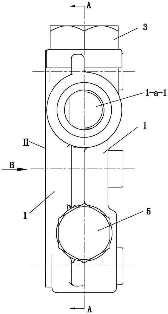
[0022] Front, back, left, right, up, down in this article figure 1 prevail.

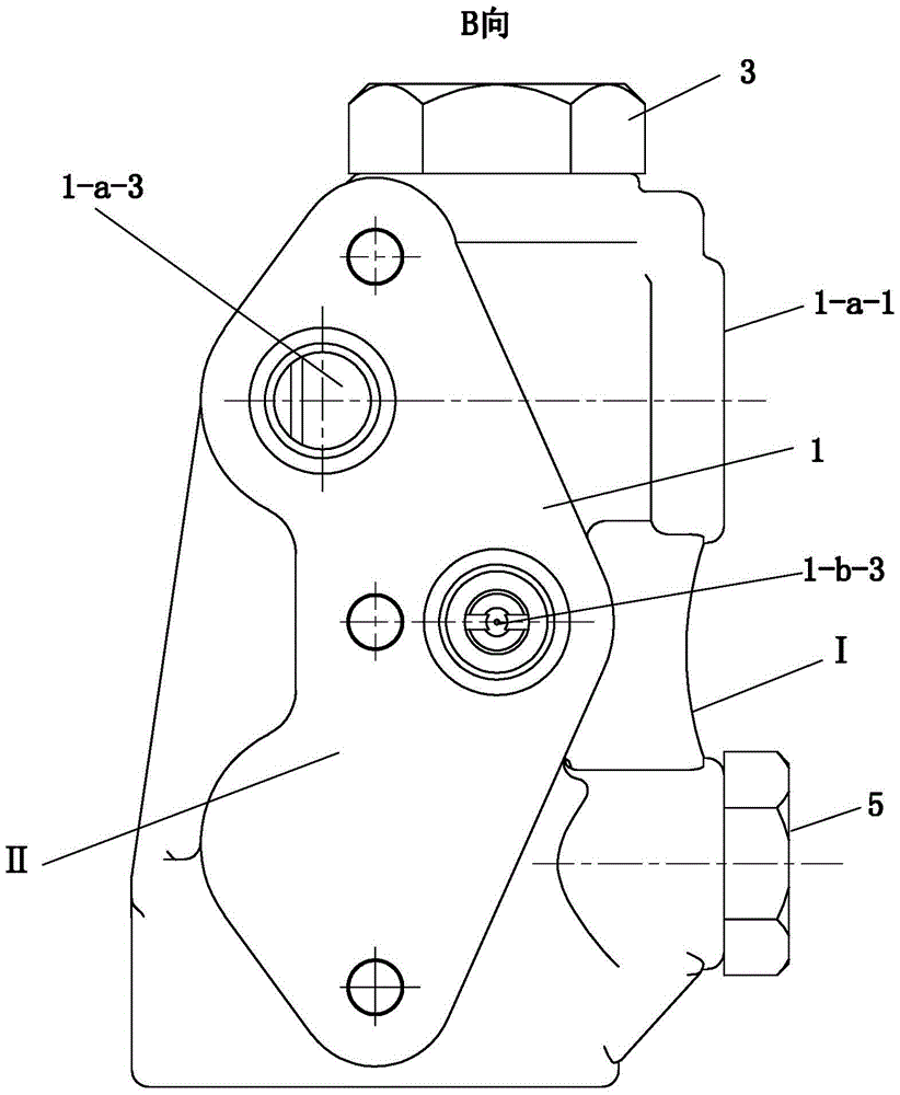
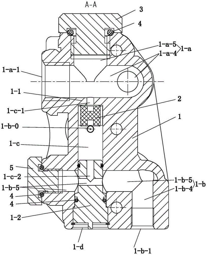
[0023] See Figure 1 to Figure 4 and Image 6 , The present embodiment has a valve body 1, and the valve body 1 is provided with a slider cavity 1-c, a common brake air supply channel 1-a and a parking brake air supply channel 1-b. Both the common brake air supply channel 1-a and the parking brake air supply channel 1-b are connected with the slider cavity 1-c, and the valve body is provided with a parking brake supply channel in the middle of the slider cavity 1-c. Gas extension to 1-b-0. A slider 2 is provided in the slider chamber 1-c.

[0024] There is a first bottom hole 1-d on the bottom surface of the valve body 1, and the first bottom hole 1-d is blocked by a post plug 1-2 to form a slider cavity 1-c on its upper part, and the first bottom hole 1- A sealing ring 4 is provided between the orifice of d and the plug 1-2. The column plug 1-2 is regarded as a part of the valve body.

[0025...

Embodiment 2

[0041] See Figure 5 , in this embodiment, the second air inlet 1-a-2 of the common brake air supply passage 1-a takes in air, and the first air inlet 1-a-1 is blocked by the upper screw plug 3, which is blocked A sealing ring 4 is provided between the opening of the upper screw plug 3 and the upper screw plug 3. The second air inlet 1-b-2 of the parking brake air supply channel 1-b takes in air, and the first air inlet 1-b-1 is blocked by the lower screw plug 5, and the blocked hole and the lower screw A sealing ring 4 is arranged between the plugs 5 . All the other are identical with embodiment 1.

Embodiment 3

[0043] This embodiment omits the view. In this embodiment, the second air inlet 1-a-2 of the common brake air supply channel 1-a is used for air intake, and the first air inlet 1-a-1 is blocked by the upper screw plug 3. Note that the parking brake air supply channel 1-b uses the first air inlet 1-b-1 to inhale air, and the second air inlet 1-b-2 is blocked by the lower screw plug 5.


PUM


Abstract

An anti-overlapping valve for a rail vehicle foundation brake device, the valve body is provided with a slider cavity, a common brake air supply channel, a parking brake air supply channel, and a parking brake air supply extension channel located in the middle of the slider cavity , the common brake air supply channel, the parking brake air supply channel and the slider cavity are connected, the slider cavity is provided with a slider, when the slider is at one end of the slider cavity, the parking brake air supply channel and The parking brake air supply extension is connected, and when the slider is at the other end of the slider cavity, the common brake air supply is connected with the parking brake air supply extension. The common brake air supply channel of the present invention communicates with the common brake cylinder, and the parking brake air supply extension channel communicates with the parking brake cylinder. If the train driver releases the air in the parking brake cylinder in advance due to improper operation or mistake, the air will enter the parking brake cylinder through the common brake air supply channel and the parking brake air supply extension channel, so as to avoid the common braking force and the parking brake cylinder. The superposition of the braking force of the vehicle ensures the safe operation of the vehicle and improves the service life of the basic braking device.

Description

technical field [0001] The invention relates to an anti-overlapping valve of a rail vehicle foundation braking device. Background technique [0002] The basic braking device is a key component of rail transit, and the braking force is applied through the basic braking device to make the train stop within a specified distance. In order to realize the common braking and parking brake of the train, the basic braking device is usually provided with a common braking cylinder and a parking braking cylinder. The parking brake cylinder uses the spring to store capacity (energy). When the train is running normally, air is always filled into the parking brake cylinder, and the compressed air overcomes the force of the spring to compress the spring and store energy for the spring. When the train brakes and stops, air is charged into the common brake cylinder to slow down the train to stop; when the train stops, the air in the common brake cylinder and the parking brake cylinder are ex...

Claims


Application Information

Patent Timeline
Patent Type & Authority Patents(China)
IPC IPC(8): B60T15/02
Inventor 韩红文何斌霍伟陈艾超郑志立
Owner CRRC CHANGZHOU TECH MARK IND CO LTD
Why Eureka
Try Eureka