Rigidity-adjustable ball joint and thrust rod assembly

A ball joint and thrust rod technology, applied to the cantilever mounted on the pivot, shaft and bearing, vehicle parts, etc. Easy to come off or break and other problems, to achieve the effect of increasing positioning effect, simple structure and convenient disassembly

Pending Publication Date: 2021-06-01
SINO TRUK JINAN POWER
View PDF9 Cites 3 Cited by
  • Summary
  • Abstract
  • Description
  • Claims
  • Application Information

AI Technical Summary

Problems solved by technology

[0006] In order to solve the above-mentioned problems that the stiffness of the thrust rod assembly cannot be adjusted, the rubber vulcanized structure is prone to tearing, the ball pin is easy to fall out or break, and the overall service life is short, the present invention provides a ball joint and a thrust rod with adjustable stiffness Assembly

Method used


Image

  • Rigidity-adjustable ball joint and thrust rod assembly
  • Rigidity-adjustable ball joint and thrust rod assembly
  • Rigidity-adjustable ball joint and thrust rod assembly

Examples


Embodiment Construction

[0032] In order to make the purpose, features and advantages of the present invention more obvious and understandable, the technical solutions in the present invention will be clearly and completely described below in conjunction with the accompanying drawings in this specific embodiment. Obviously, the implementation described below Examples are only some embodiments of the present invention, but not all embodiments. Based on the embodiments in this patent, all other embodiments obtained by persons of ordinary skill in the art without creative efforts fall within the protection scope of this patent.

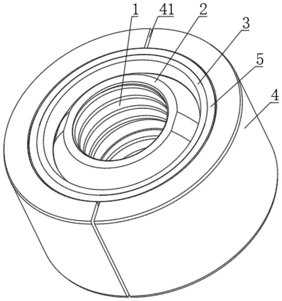
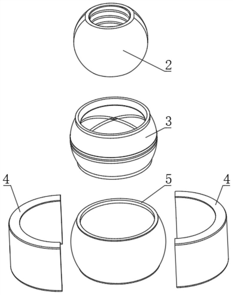
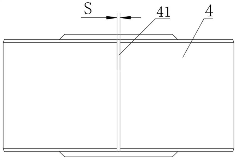
[0033] As shown in the accompanying drawings, a ball joint with adjustable stiffness includes a spherical ball 2, an annular bearing outer ring 3 and two semi-annular steel stiffness adjustment sleeves 4; the outer surface of the ball 2 is in contact with the bearing The inner surface of the outer ring 3 is matched, and the ball 2 can freely rotate universally relative to the be...


PUM


Abstract

The invention discloses a rigidity-adjustable ball joint and thrust rod assembly, and belongs to the technical field of automobile suspension systems. The assembly comprises a thrust rod bracket, a pin shaft, a thrust rod, a ball body, a bearing outer ring and rigidity adjusting sleeves, wherein the ball body is in sliding universal connection with the bearing outer ring; the bearing outer ring is connected with the rigidity adjusting sleeves through an elastic layer; adjusting gaps are formed by the corresponding end faces of the rigidity adjusting sleeves on the two sides; the thrust rod and the rigidity adjusting sleeves are fixedly mounted; and the pin shaft is inserted into a mounting shaft hole and is connected with the thrust rod bracket. Free universal rotation of the thrust rod assembly is achieved through a ball joint, torsion stress of the elastic layer is released, and the elastic layer is only subjected to pressure load; the elastic layer achieves the buffering function of the thrust rod assembly, and the impact load in the force transmission process of the thrust rod is reduced; and the rigidity adjusting sleeves are provided with the adjusting gap, so that rigidity adjustment of the thrust rod assembly is achieved, the reliability of the thrust rod assembly is improved, the service life is prolonged, meanwhile, flexible connection of a suspension system and an axle assembly is achieved, and the comfort of a whole vehicle is improved.

Description

technical field [0001] The invention belongs to the technical field of automobile suspension systems, in particular to a ball joint and thrust rod assembly with adjustable stiffness. Background technique [0002] The rear suspension system of heavy-duty commercial vehicles generally adopts a balanced suspension. The balance shaft assembly is arranged in the middle of the balanced suspension system, and the connection with the axle is realized through the upper and lower thrust rod assemblies. The beating trajectory and force transmission of the drive axle are mainly It is realized through the upper and lower thrust rod assemblies. According to the force requirements, the balanced suspension system generally arranges six thrust rod assemblies, including two on the upper side and four on the lower side. Based on the above purpose, the connection between the thrust rod assembly and the bridge assembly is generally a hinged structure. [0003] The connection between the traditi...

Claims


Application Information

Patent Timeline
Patent Type & Authority Applications(China)
IPC IPC(8): F16C11/06F16C11/08B60G7/00
CPCF16C11/0604F16C11/0614F16C11/068F16C11/083F16C11/0695B60G7/005B60G7/00
Inventor 杨永祥郭纪泰孙长春郭经顺栾会磊张邦为苑立宽
Owner SINO TRUK JINAN POWER
Why Eureka
Try Eureka