Car battery installation structure

A technology for mounting structures and automobile batteries, which is applied to superstructures, subassemblies of superstructures, vehicle components, etc., which can solve problems such as large input force and release of hooks, and achieve the effect of inhibiting fractures

Active Publication Date: 2019-12-13
HONDA MOTOR CO LTD
View PDF12 Cites 0 Cited by
  • Summary
  • Abstract
  • Description
  • Claims
  • Application Information

AI Technical Summary

Problems solved by technology

At this time, the locking member locked by the hook of the battery clamp bolt of the battery base receives a large input force, which may cause the hook to release the locking.

Method used


Image

  • Car battery installation structure
  • Car battery installation structure
  • Car battery installation structure

Examples


Embodiment Construction

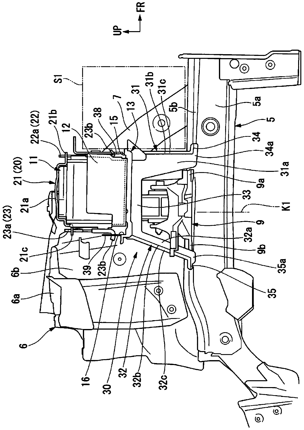
[0030] One embodiment of the present invention will be described below based on the drawings. In addition, directions such as front, rear, left, and right described below are the same as directions of a vehicle described below, unless otherwise specified. In addition, arrows FR indicating the front of the vehicle, arrows LH indicating the left of the vehicle, and arrows UP indicating the upward direction of the vehicle are shown at appropriate places in the drawings used in the following description.

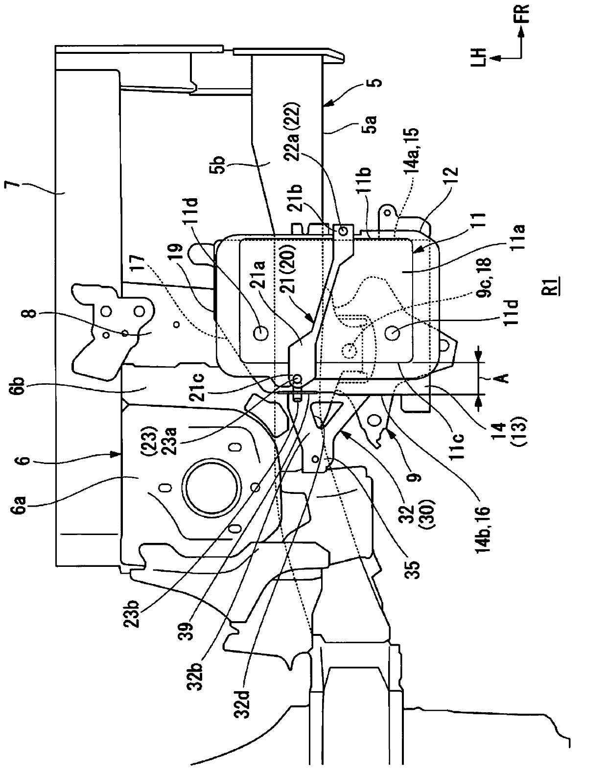
[0031] Such as figure 1 , figure 2 As shown, at the front of the vehicle body of the automobile, on both sides of the vehicle width direction (left and right direction) of the engine room R1 in front of the compartment, there are provided with: a front side frame 5 extending along the front and rear directions of the vehicle; and a shock absorber housing 6 , which supports the upper end of a suspension damper (not shown) located above the front side frame 5 .

[0032] Upper ...


PUM


Abstract

According to the present invention, there is provided an automobile battery mounting structure in which a leg (30) of a battery base (13) is formed of a metal plate intersecting a vehicle front-rear direction, and the width of the vehicle is larger, (34, 35) is provided at the lower end of the leg (30), and the lower bent portion (34, 35) is fixed to the front side frame (5), and the lower end (38b) is provided at the upper end of the leg portion (30), and the upper end engaging portion (38, 39) is locked to the upper end of the opening (31d, 32d) Battery clamping parts. Accordingly, it is possible to maintain the engagement of the hook portion of the battery gripping bolt with respect to the battery base locking member when the vehicle collides with the front side.

Description

technical field [0001] The invention relates to an automobile battery installation structure. Background technique [0002] In the automobile battery mounting structure of Patent Document 1, the front part of the battery base is fixed to the engine mount, the outer part of the battery base is fixed to the side wall of the engine room, and the rear part of the battery base is fixed to the front through the legs. Front side frame. In particular, the legs are made of easily deformable plates and formed into a mountain shape with a convex cross section. Therefore, in the event of a frontal collision of the vehicle, the deformation of the front frame will not be hindered, and the battery can be stably supported. [0003] Patent Document 1: Japanese Invention Patent Grant Gazette No. 5494001 [0004] The technical problem to be solved by the invention [0005] However, when the front side frame deforms upward and the engine mount moves upward during a frontal collision of the v...

Claims


Application Information

Patent Timeline
Patent Type & Authority Patents(China)
IPC IPC(8): B60R16/04B62D25/08
CPCB60R16/04B62D25/082
Inventor 中村邦彦藤森胜哉岩部竜男
Owner HONDA MOTOR CO LTD
Why Eureka
Try Eureka