Low-altitude illuminating lamp structure for bridge

A technology of lighting lamps and lighting fixtures, which is applied to lighting devices, fixed lighting devices, lighting and heating equipment, etc., can solve the problems of the service life of bridge low-altitude lighting lamps, cumbersome disassembly of lamp bodies, troublesome staff, etc., and achieve simple structure , Convenient operation, and the effect of improving stability

Active Publication Date: 2017-05-31
盐城明钰科技有限公司
View PDF5 Cites 2 Cited by
  • Summary
  • Abstract
  • Description
  • Claims
  • Application Information

AI Technical Summary

Problems solved by technology

[0002] With the progress and prosperity of the times, low-altitude lighting in bridges has been widely used. It makes the bridges at night no longer dark, helps people appear at night, and brings certain convenience. Usually for To meet the lighting needs very well, it requires more installation of lamps. Since it is installed outdoors, it is greatly affected by corrosion, wind, and vibration. Therefore, the service life of bridge low-altitude lighting is seriously affected. This is for bridge low-altitude lighting. The maintenance of the lamp needs to be fast and convenient. In order to prolong the service life of the existing bridge low-altitude lighting lamps, it is usually installed directly in the bridge body, so that the protection of the lamp body by the bridge body prolongs the service life, but it is extremely difficult to maintain. When the lamp body is damaged, it is cumbersome to disassemble the lamp body, which brings trouble to the staff

Method used


Image

  • Low-altitude illuminating lamp structure for bridge
  • Low-altitude illuminating lamp structure for bridge
  • Low-altitude illuminating lamp structure for bridge

Examples


Embodiment Construction

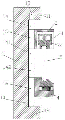
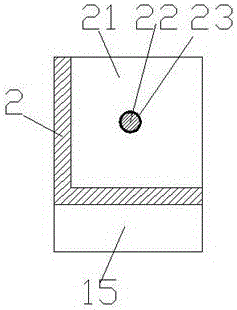
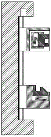
[0021] Such as Figure 1-Figure 7 As shown, a bridge low-altitude lighting structure of the present invention includes a frame body 1, and the frame body 1 is provided with a first wedging block 11 and a second wedging block 12, and the inside of the first wedging block 11 is An electric motor 13 is fixed, and the bottom of the electric motor 13 is screwed with a screw rod 14, and the screw rod 14 extends toward the second wedging block 12 and connects with the second wedging block 12. screw connection, the screw rod 14 is made up of a first screw rod 141 and a second screw rod 142, and the first screw rod 141 and the second screw rod 142 are set on the opposite side of the screw thread, so that the The first sliding block 15 and the second sliding block 16 move closer to or away from each other, and the first screw rod 141 and the second screw rod 142 are threadedly connected with the first sliding block 15 and the second sliding block respectively. 16. The first sliding blo...


PUM


Abstract

The invention discloses a low-altitude illuminating lamp structure for a bridge. The low-altitude illuminating lamp structure comprises a rack body. A first wedge block and a second wedge block are arranged on the rack body. An electric motor is fixedly arranged in the first wedge block. A spiral rod is connected to the bottom of the electric motor in a rotary manner. The spiral rod extends toward one side of the second wedge block and is connected with the second wedge block in a rotary manner. The spiral rod is composed of a first spiral rod body and a second spiral rod body. A first slide block and a second slide block are in threaded connection to the first spiral rod body and the second spiral rod body correspondingly. A slide rail is connected between the first slide block and the rack body in a sliding and matched manner, and a slide rail is connected between the second slide block and the rack body in a sliding and matched manner. The low-altitude illuminating lamp structure is convenient and fast to operate, precise in butt joint, high in stability and convenient to disassemble and assemble.

Description

technical field [0001] The invention relates to the technical field of bridges, in particular to a bridge low-altitude lighting structure. Background technique [0002] With the progress and prosperity of the times, low-altitude lighting in bridges has been widely used. It makes the bridges at night no longer dark, helps people appear at night, and brings certain convenience. Usually for To meet the lighting needs very well, it requires more installation of lamps. Since it is installed outdoors, it is greatly affected by corrosion, wind, and vibration. Therefore, the service life of bridge low-altitude lighting is seriously affected. This is for bridge low-altitude lighting. The maintenance of the lamp needs to be fast and convenient. In order to prolong the service life of the existing bridge low-altitude lighting lamps, it is usually installed directly in the bridge body, so that the protection of the lamp body through the bridge body prolongs the service life, but it is e...

Claims


Application Information

Patent Timeline
Patent Type & Authority Applications(China)
IPC IPC(8): F21S8/00F21V15/04F21V17/12F21V17/16F21V17/18
CPCF21S8/00F21V15/04F21V17/12F21V17/162F21V17/18
Inventor 朱云仙
Owner 盐城明钰科技有限公司
Why Eureka
Try Eureka