A power device knob

A technology for electrical equipment and knobs, applied in circuits, electrical switches, electrical components, etc., can solve the problems of inconvenient inspection and maintenance, easy to mis-rotate operation, easy to wear and fail, etc. good safety effect

Active Publication Date: 2018-11-09
青岛大方新瑞网络科技有限公司
View PDF3 Cites 0 Cited by
  • Summary
  • Abstract
  • Description
  • Claims
  • Application Information

AI Technical Summary

Problems solved by technology

[0004] The purpose of the present invention is to provide a knob for electric equipment to solve the problems existing in the prior art, such as easy wear and failure, inconvenient inspection and maintenance, easy wrong rotation operation, etc.

Method used


Image

  • A power device knob
  • A power device knob

Examples


Embodiment 1

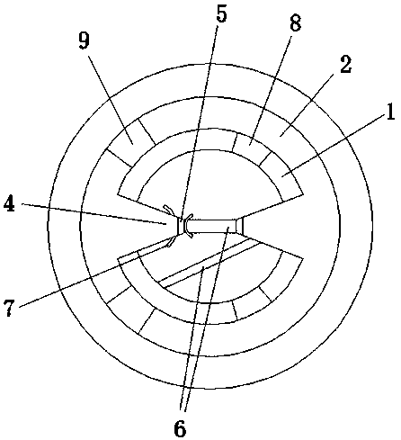
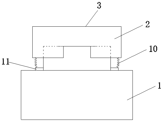
[0026] A power device knob such as figure 1 and figure 2 As shown, it includes a cylindrical inner ring tube 1, and the longitudinal section of the inner ring tube 1 is set in a "convex" shape. The top is provided with a closed circular plate 3;

[0027] The lower surface of the closed circular plate 3 is connected with two sliders 4 with a trapezoidal transverse section, the two sliders 4 are evenly and symmetrically distributed, and the ends of the sliders 4 are respectively connected with insulating sheets 5 extending downward;

[0028] The lower part of the inner ring cylinder 1 is provided with wire holes, and the lines of the wires 6 extend into the inner ring cylinder 1 through the wire holes respectively. The ends of the wires 6 are respectively connected with a conductive sheet 7, and the two conductive sheets 7 are in contact with each other. When the outer cover ring tube 2 rotates outside the inner ring tube 1, the slider 4 is driven to move, so as to drive the ...

Embodiment 2

[0033] A knob for electric equipment is similar to Embodiment 1, the difference is that the closed circular plate 3 and the outer cover ring cylinder 2 are arranged in an integrated structure.

[0034] Preferably, the insulating sheet 5 is arranged in the shape of a rectangular strip.

[0035] Preferably, the wire hole is set as a circular hole.

[0036] Preferably, the number of wire holes is four.

[0037] Preferably, an annular protective ring is provided at the edge of the wire hole.

[0038] Preferably, the number of the inner notch 8 and the outer notch 9 is two respectively.

[0039] Preferably, the inner notches 8 are evenly and symmetrically distributed on the upper side wall of the inner ring tube 1 , and the outer notches 9 are evenly and symmetrically distributed on the side wall of the outer cover ring tube 2 .

[0040] Preferably, both the inner notch 8 and the outer notch 9 are set in a rectangle.

[0041] Preferably, the conductive sheet 7 is configured as ...


PUM


Abstract

The invention discloses a power equipment knob. The power equipment knob comprises a cylindrical inner ring barrel, wherein the longitudinal section of the inner ring barrel is set to be convex; the outer side of the upper part of the inner ring barrel is sleeved with a cylindrical outer cover ring barrel; the outer cover ring barrel is connected with a sliding block; the end portion of the sliding block is connected with an insulating sheet; wire holes are formed in the lower part of the inner ring barrel; a wire loop extends into the inner ring barrel through the wire holes respectively; the wire loop is provided with a breaking part inside the inner ring barrel; wire end portions on two sides of the breaking part are connected with a conductive sheet separately; the two conductive sheets are in contact with each other; an inner gap is formed in the side wall of the upper part of the inner ring barrel, and an outer gap correspondingly matched with the inner gap is formed in the side wall of the outer cover ring barrel; the bottom of the edge of the outer cover ring barrel is connected with the upper end of a corrugated sleeve pipe; the corrugated sleeve pipe is arranged outside the inner ring barrel in a sleeving manner; the lower end of the corrugated sleeve pipe is connected with a gasket; the bottom surface of the gasket is in contact with the upper wall of the lower part of the inner ring barrel. The power equipment knob is convenient to check and maintain, can prevent false rotation operation, and is high in safety.

Description

technical field [0001] The invention relates to the technical field of electric equipment, in particular to a knob for electric equipment. Background technique [0002] At present, due to the continuous development of the power industry and civil equipment, knobs for power equipment are also widely used. [0003] Existing knobs for power equipment mostly use a single structure in which two conductors are rotated relative to each other to touch or separate, which often has problems such as easy wear and failure, inconvenient inspection and maintenance, and easy wrong rotation operation. Contents of the invention [0004] The purpose of the present invention is to provide a knob for electric equipment to solve the problems existing in the prior art, such as easy wear and failure, inconvenient inspection and maintenance, and easy wrong rotation operation. [0005] In order to achieve the above object, the method of the present invention provides a power equipment knob, which...

Claims


Application Information

Patent Timeline
Patent Type & Authority Patents(China)
IPC IPC(8): H01H19/08H01H19/14H01H19/04
CPCH01H19/04H01H19/08H01H19/14
Inventor 徐广鑫
Owner 青岛大方新瑞网络科技有限公司
Why Eureka
Try Eureka