Low-voltage electrical cabinet convenient for busbar maintenance and maintenance method thereof

A technology of low-voltage electrical cabinets and electrical cabinets, which is applied in the direction of electrical components, photovoltaic power generation, busbar/line layout, etc., which can solve problems such as inconvenient inspection, difficult inspection of busbars, and distorted posture, so as to achieve the effect of convenient inspection and maintenance

Inactive Publication Date: 2022-08-09
深圳宏伟时代自控有限公司
View PDF0 Cites 0 Cited by
  • Summary
  • Abstract
  • Description
  • Claims
  • Application Information

AI Technical Summary

Problems solved by technology

[0003] At present, the busbar is usually installed on the top of the low-voltage electrical cabinet in the market. When the maintenance personnel overhaul the electrical cabinet, there are many inspection items, among which the busbar needs to be inspected. The main inspection is to check whether the paint of the busbar is complete and whether the phase mark is correct and obvious. And check whether the terminal posts, busbar joints are tight, whether there is corrosion and overheating phenomenon, because the shell of the existing electrical cabinet is generally designed as a rectangular cabinet, and the busbar at the top is difficult to check, and tools are needed. Looking at the top busbar from the inside, its posture is relatively distorted. Long-term inspection will cause strain on the body, and inspection is inconvenient. Therefore, we propose a low-voltage electrical cabinet and its maintenance method that are convenient for busbar maintenance.

Method used


Image

  • Low-voltage electrical cabinet convenient for busbar maintenance and maintenance method thereof
  • Low-voltage electrical cabinet convenient for busbar maintenance and maintenance method thereof
  • Low-voltage electrical cabinet convenient for busbar maintenance and maintenance method thereof

Examples


Embodiment 1

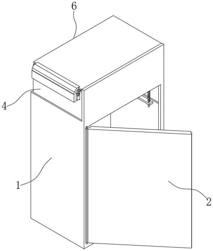
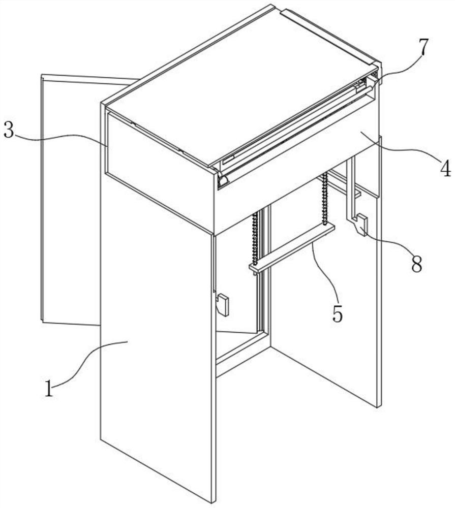
[0030] see figure 1 and figure 2 , a low-voltage electrical cabinet that is convenient for busbar maintenance in the figure includes an electrical cabinet shell 1, a support frame 8 fixed on the inner side of the electrical cabinet shell 1, and a cabinet is installed on one side of the electrical cabinet shell 1 The door 2, and the top of the three sides of the electrical cabinet shell 1 away from the cabinet door 2 is provided with a receiving port 3, the receiving port 3 is provided with a U-shaped plate 4, and the inner side of the U-shaped plate 4 is installed with all the The connecting piece 5 is fixed to the inner wall of the electrical cabinet shell 1. A driving mechanism 7 is installed on the top of the U-shaped plate 4, and the driving mechanism 7 is used for the movement of the movable top cover 6. Busbars are installed.

[0031] In this solution, the electrical cabinet shell 1 is improved, a receiving port 3 for the movement of the U-shaped plate 4 is opened at ...

Embodiment 2

[0048] see Image 6 and Figure 7 In this embodiment, the first embodiment is further described. The clip 21 in the figure includes a docking rod 24 that is slidably inserted into the outer end of the U-shaped frame 16, and the bottom end of the docking rod 24 is located at the sliding port 19. A pressure plate 25 is fixed inside the docking rod 24 , a compression spring 26 for pushing the pressure plate 25 downward is sleeved on the outside of the docking rod 24 , a limiting cap 27 is fixed on the top of the docking rod 24 , and the outer end of the slider 20 is Rounded corners are formed, and both ends of the pressing plate 25 are formed with rounded corners.

[0049] It should be noted that: when the second U-shaped frame 18 is pulled out, the slider 20 and the outer end of the pressure plate 25 will be abutted, so that the pressure plate 25 will move up, so that the slider 20 will move above the card interface 22, and will be pressed against the spring 26. Under the acti...

Embodiment 3

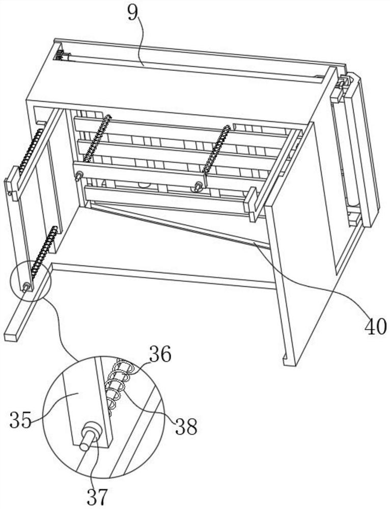
[0054] see image 3 and Image 6 , this embodiment further describes other embodiments, in the figure, a linkage rod 39 is fixed on the outer side of the moving shaft 13, and the inner side of the low-voltage electrical cabinet is provided with a chute 40 that slides and docks with the linkage rod 39;

[0055] It should be noted that: when the moving shaft 13 moves, the linkage rod 39 moves in the chute 40, so that the U-shaped plate 4 can be adjusted up and down, making the adjustment more convenient.

[0056] It should be noted that: when the second U-shaped frame 18 is inserted into the first U-shaped frame 16, it extends under the pressing plate 25 through the limit plate 32, and is clamped with the bayonet 34 through the trapezoidal block 33 at the outer end, so as to realize the limit The position limit of the position plate 32 also realizes the position limit after the U-shaped frame 2 18 is retracted.


PUM


Abstract

The invention discloses a low-voltage electrical cabinet convenient for busbar maintenance and a maintenance method thereof, relates to the technical field of low-voltage electrical cabinet maintenance, and solves the problem that a busbar in an existing low-voltage electrical cabinet is difficult to maintain, the low-voltage electrical cabinet comprises an electrical cabinet shell and a support frame fixed on the inner side of the electrical cabinet shell, and a cabinet door is mounted on one side of the electrical cabinet shell. The top of the three sides, away from the cabinet door, of the electrical cabinet shell is provided with a storage opening, a U-shaped plate is arranged in the storage opening, the inner side of the U-shaped plate is provided with a connecting piece fixed to the inner wall of the electrical cabinet shell, the top of the U-shaped plate is provided with a driving mechanism, and the driving mechanism is used for moving the movable top cover. According to the electrical cabinet, the electrical cabinet shell is optimized, the U-shaped plate is designed so that the electrical cabinet can ascend and descend, the busbar in the electrical cabinet body can be protruded, meanwhile, the movable top cover is driven by the driving mechanism to move outwards, and personnel can conveniently check and overhaul the busbar on the top.

Description

technical field [0001] The invention relates to the technical field of maintenance of low-voltage electrical cabinets, in particular to a low-voltage electrical cabinet which is convenient for busbar maintenance and a maintenance method thereof. Background technique [0002] The busbar refers to the copper or aluminum bar that connects the general switch in the electrical cabinet and the switch in each branch circuit in the power supply system. The surface is insulated, and the main function is to use it as a wire. [0003] At present, the busbar is usually installed on the top of the low-voltage electrical cabinet in the market. When the maintenance personnel overhaul the electrical cabinet, there are many inspection items. Among them, the busbar needs to be inspected. The main inspection is to check whether the busbar paint is complete and whether the phase mark is correct and obvious. And check whether the terminals, busbar joints are tight, and whether there is corrosio...

Claims


Application Information

Patent Timeline
Patent Type & Authority Applications(China)
IPC IPC(8): H02B1/30H02B1/20H02B1/34H02B3/00
CPCH02B1/30H02B1/306H02B1/20H02B1/202H02B1/34H02B3/00Y02E10/50
Inventor 朱雅叶黄功桥
Owner 深圳宏伟时代自控有限公司
Why Eureka
Try Eureka