A switch input circuit for relay protection tester

A technology of switch input and relay protection device, applied in the field of flat circuit, can solve the problems of damage of relay protection device, reduce the efficiency of work, etc., and achieve the effect of reducing external wiring

Active Publication Date: 2020-05-26
XIANGTAN UNIV
View PDF5 Cites 0 Cited by
  • Summary
  • Abstract
  • Description
  • Claims
  • Application Information

AI Technical Summary

Problems solved by technology

[0004] At present, the wiring of the relay protection tester needs to be set in advance according to the form of binary input. On the one hand, this method reduces the work efficiency. damage

Method used


Image

  • A switch input circuit for relay protection tester
  • A switch input circuit for relay protection tester
  • A switch input circuit for relay protection tester

Examples


Embodiment Construction

[0018] The present invention will be further described below in conjunction with the accompanying drawings.

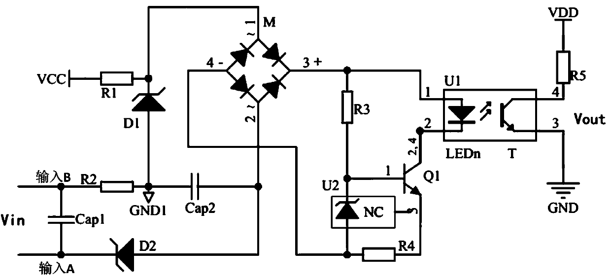
[0019] figure 1 It is the schematic diagram of the digital input circuit. VCC is connected to +12V power supply, VDD is connected to +3.3V power supply, and VCC and VDD do not share the same ground. +12V is connected to the cathode of 8.2V Zener diode (model ZPD8.2) D1 via 1K resistor R1, and the anode of D1 is connected to the ground GND1 referenced by +12V. Q1 is a triode FZT658 with a withstand voltage of 400V, U1 is a photocoupler PS2703, M is a bridge rectifier MB6S with a reverse withstand voltage of 600V, and U2 is a regulated power supply LM385M3 with a fixed voltage difference between the negative and positive electrodes of 1.2V , Zener diode D2 is ZPD5.1. In the normal state, the output of the circuit is in a high-impedance state, and the initial state of the rectifier bridge is in the bridge balance state, that is, the voltages of the AC input terminals (...


PUM


Abstract

The invention discloses an on-off input circuit for a relay protection testing device. The circuit consists of a voltage stabilizing diode, a rectification bridge circuit, a photoelectric coupler circuit, a triode switching circuit, a filter capacitor and a voltage stabilizing reference power circuit. The on-off input circuit for the relay protection testing device is self-adaptive about various types of the input patterns, and the pre-configuration does not need to be executed; and the on-off input circuit for the relay protection testing device is self-adaptive about the polarity of the active input, even the reverse connection can be correctly identified, and the potential safety hazard cannot be caused by the polarity of the input. The on-off input circuit for the relay protection testing device is provided with the potential output, and is capable of providing the power for the high-speed output of the Darlington tube type, and reducing the external connections.

Description

technical field [0001] The invention relates to the field of flat circuits, in particular to a switching value input circuit of a relay protection tester. Background technique [0002] In the power protection industry, relay protection devices are widely used and indispensable. Whether it is as small as some electric devices (such as generators, power supply lines), or as large as the entire power system, relay protection devices are required to provide fault warning signals, or directly and automatically control circuit breakers to issue trip instructions to ensure the safety of power equipment . Therefore, it is necessary to regularly overhaul and maintain the relay protection device. [0003] The emergence of relay protection tester has brought great convenience for debugging relay protection devices. The relay protection tester has a binary input circuit, which can receive the binary output from the relay protection device and reflect its current state. In the field,...

Claims


Application Information

Patent Timeline
Patent Type & Authority Patents(China)
IPC IPC(8): H03K19/003
CPCH03K19/00307
Inventor 朱江徐雁冰田淑娟印峰许海霞邓清勇刘昊霖裴廷睿
Owner XIANGTAN UNIV
Why Eureka
Try Eureka