Rotary camera mechanism with protective shell

A technology of rotating cameras and cameras, which is applied in the direction of supporting machines, image communications, mechanical equipment, etc., can solve the problems of limited application range, easy accumulation of dust, and troublesome adjustments, and achieve the effects of ensuring service life, protecting cameras, and facilitating installation and disassembly

Active Publication Date: 2017-05-31
百捷智达科技有限公司
View PDF5 Cites 10 Cited by
  • Summary
  • Abstract
  • Description
  • Claims
  • Application Information

AI Technical Summary

Problems solved by technology

[0004] The existing cameras are all fixed on the shelf, and their positions cannot be adjusted. In this way, when they are used, the positions do not correspond, and they can only be reinstalled and adjusted, so that the scope of application is limited, the adjustment is troublesome, and the effect is not ideal.
[0005] At the same time, the existing cameras are generally exposed outside, and dust is easy to accumulate when placed for a long time, which affects the use

Method used


Image

  • Rotary camera mechanism with protective shell
  • Rotary camera mechanism with protective shell
  • Rotary camera mechanism with protective shell

Examples


Embodiment Construction

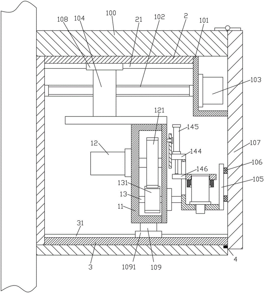
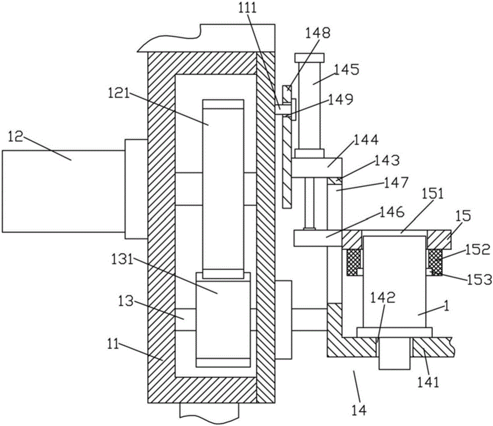
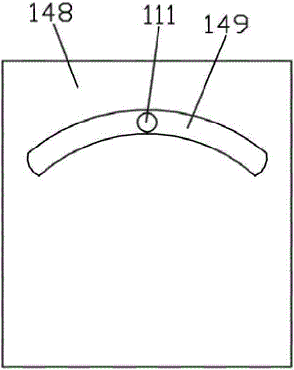
[0022] Examples, see e.g. Figure 1 to Figure 3 As shown, a rotatable camera mechanism with a protective housing includes a protective box 100 and a camera 1, the protective box 100 is fixed on the wall, and the right end of the bottom surface of the top plate of the protective box 100 is fixed with a connecting frame 101, One end of the upper transmission screw 102 is hinged on the left side plate of the protection box 100, and the other end of the upper transmission screw 102 is hinged on the connecting frame 101, and the connecting frame 101 is fixed with a mobile motor 103. The output shaft of the mobile motor 103 is a flower. The key shaft and the spline shaft are inserted into the spline hole at one end of the upper transmission screw 102, the upper moving block 104 is screwed into the upper transmission screw 102, and the bottom end of the upper moving block 104 is fixed on the top of the drive box 11 , the drive box 11 is in the protection box 100, the upper outer side...


PUM


Abstract

The invention discloses a rotary camera mechanism with a protective shell. The rotary camera mechanism comprises a protective box body and a camera. The protective box body is fixed on a wall surface. A connecting frame is fixed at the right end of the bottom surface of the top plate of the protective box body. One end of an upper drive screw is hinged on a left side plate of the protective box body and the other end of the upper drive screw is hinged on the connecting frame. A mobile motor is fixed on the connecting frame. An output shaft of the mobile motor is a spline shaft. The end of the spline shaft sleeved on the upper drive screw is equipped with a spline hole. An upper mobile block is screwed in the upper drive screw. The bottom end of the upper mobile block is fixed on the top of a drive box body. The drive box body is located in the protective box body. A drive servo motor is fixed on the outer side wall of the upper part of the drive box body. According to the rotary camera mechanism, the camera can automatically rotates to stretch out or into the protective box body, so when the rotary camera mechanism is not used, dust is not accumulated; the camera is protected; the service life of the camera is ensured; and the camera can mounted and dismounted conveniently.

Description

[0001] Technical field: [0002] The invention relates to the technical field of optical instruments and equipment, in particular to a rotatable camera mechanism with a protective housing. [0003] Background technique: [0004] Existing cameras are all fixed on the shelf, and their positions cannot be adjusted. Like this, when in use, when the positions do not correspond, they can only be reinstalled and adjusted, so that the scope of application is limited, the adjustment is cumbersome, and the effect is not ideal. [0005] At the same time, the existing cameras are generally exposed outside, and dust is easy to accumulate when placed for a long time, which affects the use. [0006] Invention content: [0007] The purpose of the present invention is to overcome the deficiencies of the prior art, and provide a rotatable camera mechanism with a protective casing, which can automatically rotate the camera and extend or enter the protective box, so that it can be used when not i...

Claims


Application Information

Patent Timeline
Patent Type & Authority Applications(China)
IPC IPC(8): H04N5/225H04N5/232F16M11/04F16M11/10F16M11/18
CPCF16M11/045F16M11/10F16M11/18H04N23/51H04N23/60
Inventor 赵鸿斌
Owner 百捷智达科技有限公司
Why Eureka
Try Eureka