Precise support rod type three-directional punching machine tool

A punching machine, rod-type technology, applied in punching machines, presses, manufacturing tools, etc., can solve the problems of high output torque requirements and electricity consumption of hydraulic stations, and achieve the effect of ensuring service life, saving electric energy, and simple structure

Active Publication Date: 2016-04-27
XINGTAI GEXIN MACHINERY EQUIP MFG CO LTD
View PDF7 Cites 33 Cited by
  • Summary
  • Abstract
  • Description
  • Claims
  • Application Information

AI Technical Summary

Problems solved by technology

Existing three-way stamping machine tools are all driven by a hydraulic station, and the sliders in each direction are driven by a separate hydraulic cylinder. This driving method has higher requirements on the output torque of the hydraulic station, which in turn consumes more electricity.

Method used


Image

  • Precise support rod type three-directional punching machine tool
  • Precise support rod type three-directional punching machine tool

Examples


Embodiment Construction

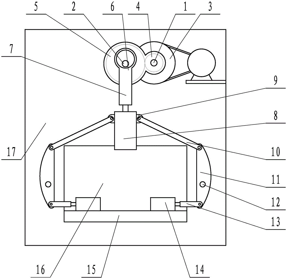
[0015] as attached figure 1 As shown, the present invention comprises transmission shaft 2, the eccentric wheel 6 that is arranged on the transmission shaft 2, the connecting rod 7 that one end is socketed with the eccentric wheel 6, the upper slider 8 that is arranged at the other end of the connecting rod 7, and the upper slider 8 connected horizontal punching device and drive device connected with transmission shaft 2. The horizontal stamping device comprises a stamping link 10, a rocker 11 hinged at one end to the stamping link 10, a slider link 13 hinged to the other end of the rocker 11, and a horizontal slider connected to the slider link 13 14. The rocker arm 11 is arranged on the frame 17 through the rocker arm shaft 12, and the other end of the stamping link 10 is hinged with the upper slider 8. The rocker shaft 12 is arranged on a side close to the slider connecting rod 13 . There are two horizontal punching devices, which are symmetrically arranged on both sides ...


PUM


Abstract

The invention relates to a precise support rod type three-directional punching machine tool. The precise support rod type three-directional punching machine tool comprises a transmission shaft, an eccentric wheel arranged on the transmission shaft, a connecting rod with one end sleeving the eccentric wheel, an upper slide block arranged at the other end of the connecting rod, a horizontal punching device connected with the upper slide block, and a driving device connected with the transmission shaft. The precise support rod type three-directional punching machine tool adopts the eccentric wheel mode to drive the upper slide block to work; meanwhile, the horizontal punching device is connected with the upper slide block; the upper slide block is used for driving; one set of driving device is only adopted; and the precise support rod type three-directional punching machine tool is simple in structure, is lower in requirement on torque input by the driving device, and saves electricity.

Description

technical field [0001] The invention relates to the field of mechanical processing, in particular to a precision strut type three-way stamping machine tool. technical background [0002] The design principle of the punching machine is to convert the circular motion into a linear motion. The main motor drives the flywheel, and the clutch drives the gear, crankshaft or eccentric gear, connecting rod, etc. to achieve the linear motion of the slider and complete the stamping work. Existing three-direction stamping machine tools are all driven by a hydraulic station, and the sliders in each direction are driven by a separate hydraulic cylinder. This driving method requires a higher output torque of the hydraulic station, which in turn consumes more electricity. Contents of the invention [0003] The technical problem to be solved by the present invention is to provide a precision strut-type three-way stamping machine tool with simple structure and power saving. [0004] The te...

Claims


Application Information

Patent Timeline
Patent Type & Authority Applications(China)
IPC IPC(8): B30B1/06B21D22/02
CPCB21D22/02B30B1/06
Inventor 汪勤利
Owner XINGTAI GEXIN MACHINERY EQUIP MFG CO LTD
Why Eureka
Try Eureka