Flexible leg structure with plane five-rod mechanism

A five-bar mechanism and flexible leg technology, which is applied in the field of planar five-bar mechanism flexible leg structure, can solve the problems of poor load-carrying capacity of series mechanism, reduced reliability and durability of parts, and joint damage, etc., so as to improve environmental adaptability, The effect of fast motion response and good kinematic performance

Active Publication Date: 2016-09-28
HEBEI UNIV OF TECH
View PDF7 Cites 11 Cited by
  • Summary
  • Abstract
  • Description
  • Claims
  • Application Information

AI Technical Summary

Problems solved by technology

[0003] At present, the leg structure of the quadruped robot is mainly based on the series mechanism. The structure of the series mechanism is simple and easy to control. However, because it is installed on the robot leg, the movement inertia of the single leg of the robot is relatively large; at the same time, the load capacity of the series mechanism is poor, so Robots are prone to problems such as joint damage, motion deviation, complete machine overturning, and motion failure under the impact of high-speed motion on the ground
The parallel mechanism has a strong bearing capacity and fast motion response, and can realize multi-directional movement of the robot's foot, but there are problems such as a small range of motion.
At the same time, at present, the single leg of a quadruped robot is generally a rigid structure or a structure with a certain passive flexibility, which makes it impossible to effectively reduce the impact of the foot end of the robot during the walking process, which will have a very negative impact on the walking stability of the robot. Moreover, the excessive impact of the foot end is easy to cause damage to the parts of the quadruped robot, reducing the reliability and durability of the parts. At the same time, this structural form causes the quadruped robot to lose energy during the walking process.

Method used


Image

  • Flexible leg structure with plane five-rod mechanism
  • Flexible leg structure with plane five-rod mechanism
  • Flexible leg structure with plane five-rod mechanism

Examples


Embodiment Construction

[0024] The present invention will be further described below in conjunction with the embodiments and accompanying drawings. The embodiment is a specific implementation carried out on the premise of the technical solution of the present invention, and provides detailed implementation methods and processes, but it is not used as a limitation to the scope of protection of the claims of the present application.

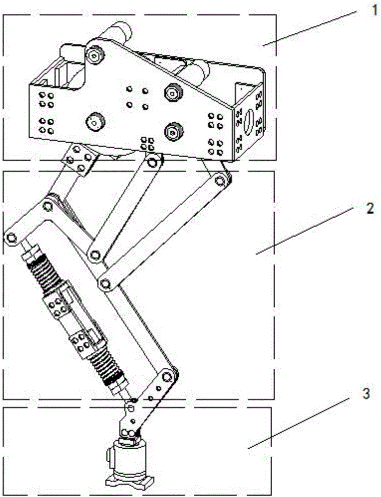
[0025] The flexible leg structure of the planar five-bar mechanism designed by the present invention (be called for short leg structure, refer to Figure 1-8 ) includes three large modules (three major parts): pitch drive joint module (referred to as pitch motion joint) 1, link structure module (referred to as link structure) 2 and toe module (referred to as toe) 3; pitch motion joint module 1 above the linkage module 2 and the toe module 3 below the linkage (see figure 1 );

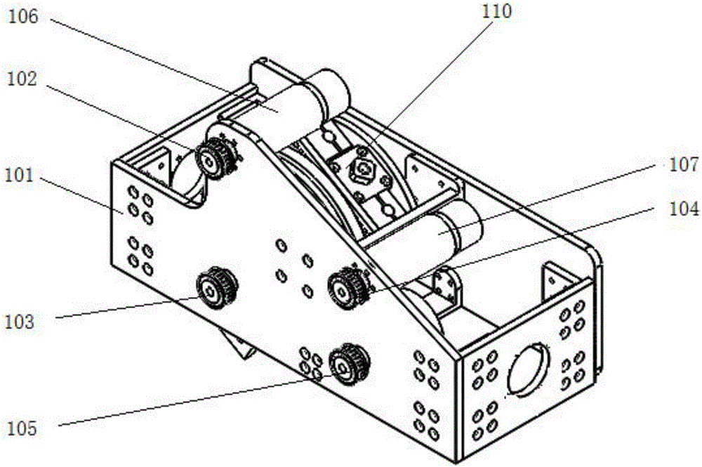
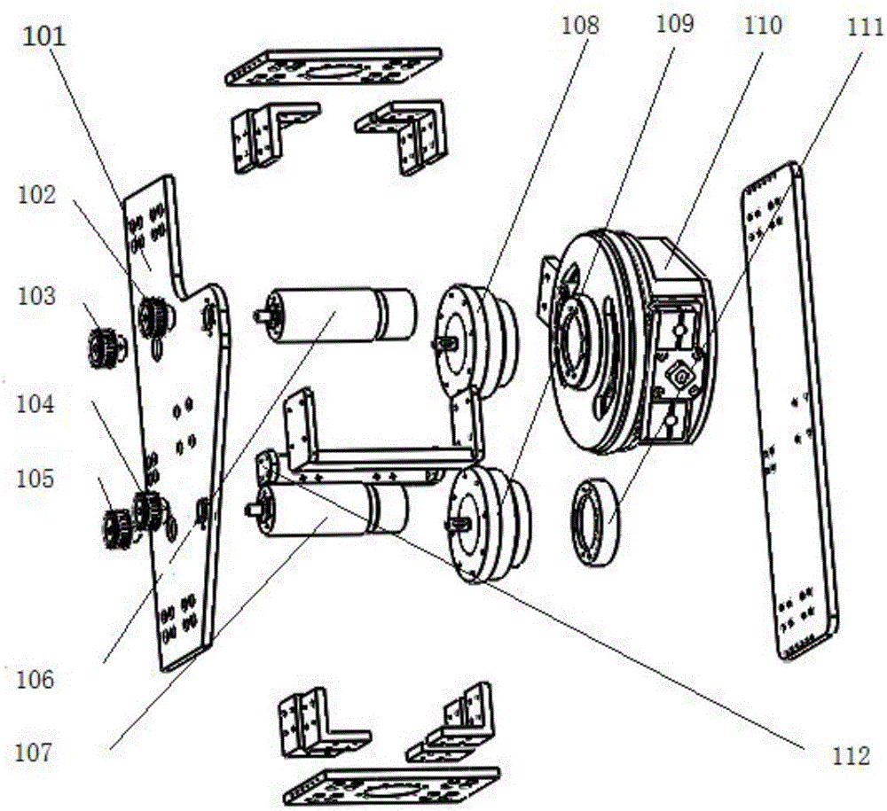
[0026] The pitch drive joint 1 (see figure 2 , image 3) includes joint support 101, No. 1 ...


PUM


Abstract

The invention discloses a flexible leg structure with a plane five-rod mechanism. The flexible leg structure is characterized by comprising a pitching drive joint, a foot tip and a connecting rod mechanism. The pitching drive joint comprises a variable stiffness driving flexible joint, a drive motor, two harmonic reducers, a supporting frame, a synchronous pulley and a synchronous belt. The foot tip comprises a three-dimensional mechanical sensor, a three-dimensional mechanical sensor support and a foot arch. The bottom of the three-dimensional mechanical sensor is connected with the three-dimensional mechanical sensor support. The bottom of the three-dimensional mechanical sensor support is connected with the foot arch. The connecting rod mechanism comprises ten hinge points (A), (B), (C), (D), (E), (F), (G), (H), (R) and (I). Connecting rods are hinged to a conventional four-rod mechanism, a four-rod mechanism with a spring rod and a plane pentagon five-rod mechanism through the ten hinge points. The hinge points (A), (R) and (I) are used for fixing the connecting rod mechanism to the pitching drive joint.

Description

technical field [0001] The invention relates to multi-legged robot platform technology, in particular to a flexible leg structure of a planar five-bar mechanism. This structure can be used for quadruped robots. Background technique [0002] In the existing multi-legged robot platform mechanism research, the mechanical structure design of the quadruped robot is the key to the whole multi-legged robot system, which directly affects the robot's load capacity and dynamic performance. The design of the mechanical structure needs to take into account many aspects. On the one hand, the robot’s load capacity and impact resistance require the robot to have a high-strength support structure and ingenious flexible buffer links; on the other hand, the characteristics of the robot’s high speed, high mobility and high adaptability require the robot to have Low motion inertia and high rigid transmission ensure fast and precise motion response. [0003] At present, the leg structure of th...

Claims


Application Information

Patent Timeline
Patent Type & Authority Applications(China)
IPC IPC(8): B62D57/032
CPCB62D57/032
Inventor 张小俊丁国帅史延雷张明路梁飞
Owner HEBEI UNIV OF TECH
Why Eureka
Try Eureka