LED constant current driving system and constant current control circuit thereof

A technology of constant current control circuit and constant current drive, which is applied in the direction of electric light sources, electrical components, electroluminescent light sources, etc., can solve the problems of low dimming accuracy, poor linearity, frequency limitation, etc., and achieve high dimming accuracy, The effect of wide adjustment range and overcoming frequency limitation

Active Publication Date: 2017-06-06
SHENZHEN SKYWORTH RGB ELECTRONICS CO LTD
View PDF3 Cites 2 Cited by
  • Summary
  • Abstract
  • Description
  • Claims
  • Application Information

AI Technical Summary

Problems solved by technology

[0004] 1. Single dimming mode, PWM digital dimming mode and analog dimming mode, the control mode can only choose one, which has certain limitations;
[0005] 2. The PWM dimming method can only adjust the frequency or duty cycle of the output signal. Although the implementation is relatively simple, it is limited by the frequency. Usually, when the frequency is too high or too low, the dimming effect is poor and the linearity is poor;
[0006] 3. The analog dimming method is greatly affected by the reference voltage, which is affected by factors such as temperature and process on the reference voltage, and the dimming accuracy is low

Method used


Image

  • LED constant current driving system and constant current control circuit thereof
  • LED constant current driving system and constant current control circuit thereof
  • LED constant current driving system and constant current control circuit thereof

Examples


Embodiment Construction

[0037] In order to make the technical problems solved by the present invention, the technical solutions adopted and the technical effects achieved clearer, the technical solutions of the embodiments of the present invention will be further described in detail below in conjunction with the accompanying drawings. Obviously, the described embodiments are only the technical solutions of the present invention. Some, but not all, embodiments. Based on the embodiments of the present invention, all other embodiments obtained by those skilled in the art without making creative efforts belong to the protection scope of the present invention.

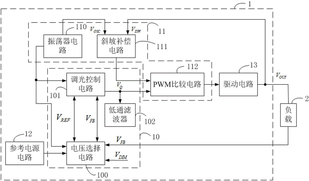
[0038] figure 1 It is a structural block diagram of the constant current control circuit of the LED constant current drive system provided by the present invention. refer to figure 1 As shown, the constant current control circuit 1 of the LED constant current drive system includes a voltage control circuit 10 and a drive signal generation circui...


PUM


Abstract

The invention discloses a constant current control circuit of an LED constant current driving system. The constant current control circuit includes a voltage control circuit used for selecting a reference voltage and a feedback voltage from a firsts reference voltage, a second reference voltage and load sampling feedback voltages according to control of a PWM control signal and a clock signal, and modulating the reference voltage and feedback voltage to output a regulating voltage signal; a driving signal generating circuit used for comparing the regulating voltage signal and a sawtooth wave signal of a fixed frequency to obtain a driving signal with a varying duty ratio, and the voltage of a load is controlled through the driving signal, so that the current of the load is kept constant. The constant current control circuit provided by the invention overcomes the problem that traditional PWM diming is limited by frequency, also solves the problem of low analog dimming precision, the load sampling feedback voltages are direct voltage signals, variation of PWM dimming signals are embodied through variation of voltage values of the load sampling feedback voltages, the regulation range is relatively wide, and the dimming precision is high.

Description

technical field [0001] The invention relates to the technical field of LED constant current drive, in particular to an LED constant current drive system and a constant current control circuit thereof. Background technique [0002] Now, the energy problem and the environmental protection problem have become the two main problems faced by human beings. LED has many advantages such as high efficiency, low consumption, environmental protection, small size and long life, and has been paid more and more attention in the lighting field. Because LED is limited by its optical and electrical characteristics, it must be supplemented with a dedicated constant current drive circuit to work properly. [0003] At present, in the integrated circuit system, the dimming modes of the LED driving system include PWM digital dimming mode, pure analog voltage dimming mode, and a mode including both PWM digital dimming and analog dimming. However, in the mode including PWM digital dimming and ana...

Claims


Application Information

Patent Timeline
Patent Type & Authority Applications(China)
IPC IPC(8): H05B33/08H05B44/00
CPCH05B45/10Y02B20/30
Inventor 孙天奇
Owner SHENZHEN SKYWORTH RGB ELECTRONICS CO LTD
Why Eureka
Try Eureka