
Oiling equipment for headrest rod of automobile seat

A technology for car seats and headrest bars, which is applied in the directions of coatings and devices for coating liquids on the surface, etc., can solve the problems of contamination of headrests, changes, waste of anti-rust oil and grease, etc., and achieve uniform grease application. Effect

Inactive Publication Date: 2017-06-09
CHONGQING YANFENG ADIENT AUTOMOTIVE COMPONENTS CO LTD
View PDF12 Cites 0 Cited by
  • Summary
  • Abstract
  • Description
  • Claims
  • Application Information

AI Technical Summary

Problems solved by technology

[0002] The headrest is an important component of the car seat. The seat headrest is usually inserted into the seat through two headrest rods. The headrest can be adjusted up and down. The adjustment force is 10N-90N. In the actual production process, the headrest is placed On the seat, the insertion and extraction force caused by internal friction is often too large, exceeding the design standard
In order to ensure that the insertion force meets the standard requirements, it is often necessary to apply lubricating grease on the headrest rod during the assembly process. At present, the more commonly used method is manual application. This application method requires a lot of manual labor. When the sponge is oiled, it is not only difficult to apply evenly, but also causes waste of anti-rust oil or anti-rust grease, or accidentally applies anti-rust oil or anti-rust grease to the headrest, polluting the headrest
In order to solve the above problems, some factories will design some oiling tools by themselves. The existing oiling devices can only do simple linear motion. When encountering a headrest rod with a certain curvature, it cannot adapt to the change of the curvature of the headrest rod. , In addition, the existing oiling tooling can only be used for one type of headrest rod, and when encountering headrest rods with different spacing, it is necessary to replace the matching tooling to be applicable

Method used


Image

  • Oiling equipment for headrest rod of automobile seat
  • Oiling equipment for headrest rod of automobile seat
  • Oiling equipment for headrest rod of automobile seat

Examples


Embodiment Construction

[0023] The present invention will be further described below in conjunction with the embodiments and accompanying drawings.

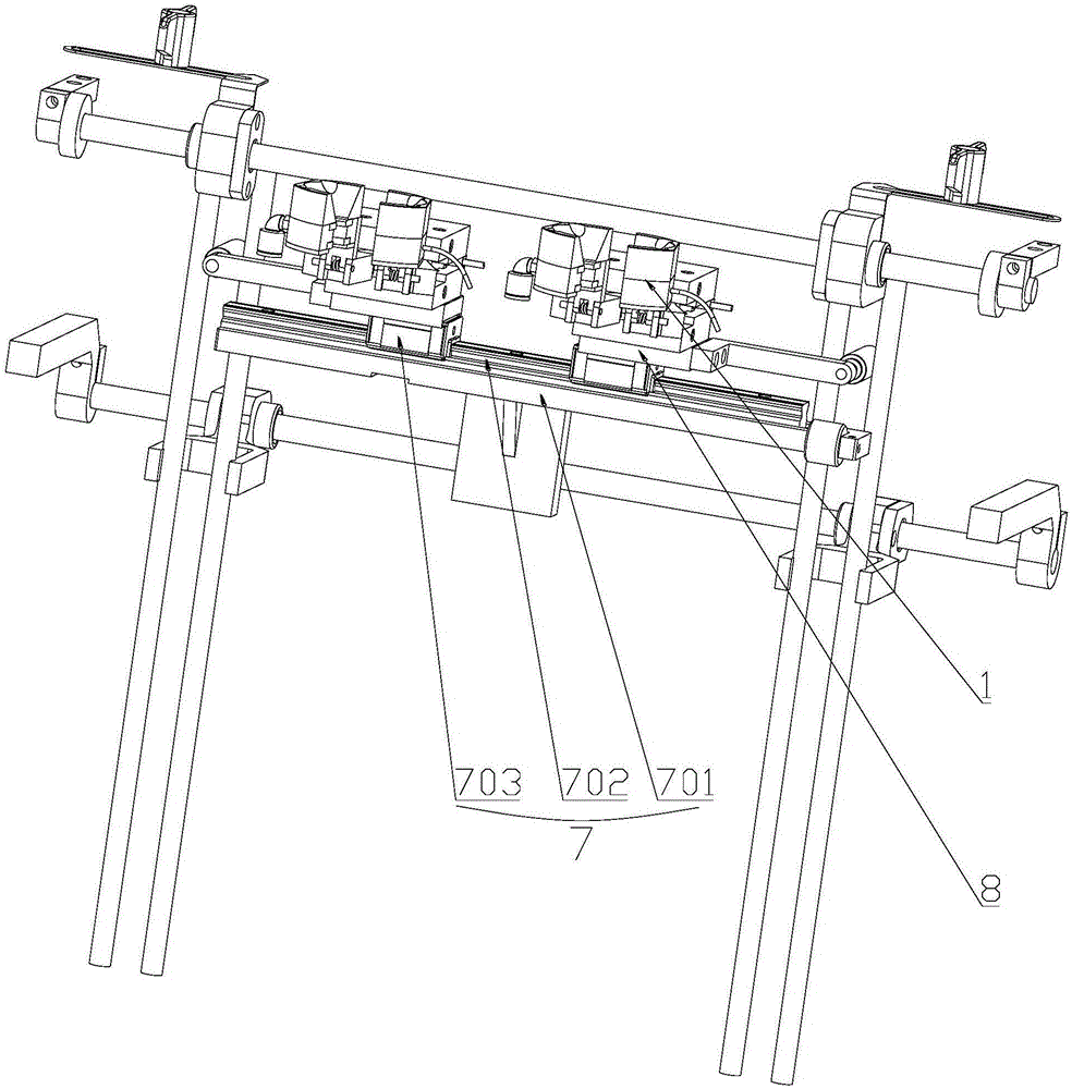
[0024] Such as Figure 1-5 As shown, a car seat headrest rod oiling device includes an x-direction linear sliding device 7, and the x-direction linear sliding device 7 is provided with two oiling devices 1;

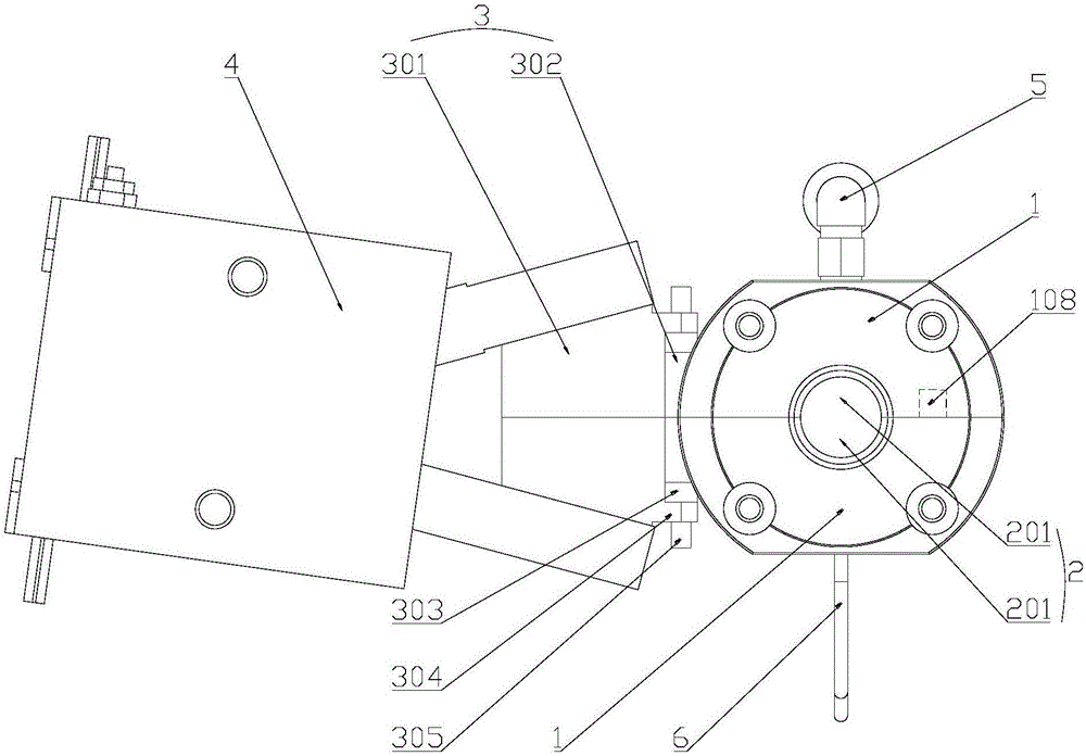
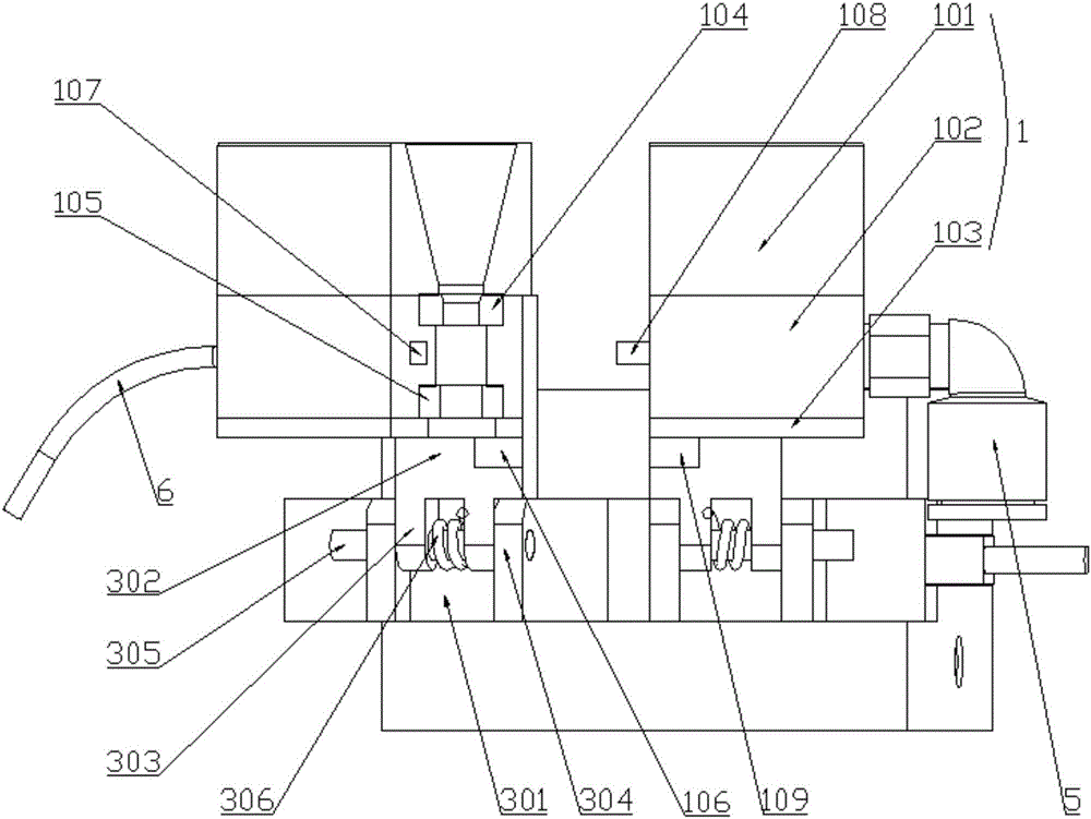
[0025] The oiling device 1 includes an opening and closing device 4, the opening and closing device 4 is provided with a floating mechanism, the floating mechanism is provided with an oiling seat, the oiling seat is provided with an oiling through hole 2, and the oiling seat is provided with an oiling through hole 2. An upper sealing gasket and a lower sealing gasket are arranged in the oil through hole 2, and the inner diameters of the upper sealing gasket and the lower sealing gasket are smaller than the aperture diameter of the oil-coated through hole 2, and all the gaps between the upper sealing gasket and the lower sealing gasket The above-me...


PUM


Abstract

The invention discloses oiling equipment for a headrest rod of an automobile seat. The equipment comprises an x-directional straight line sliding device. Two oiling devices are arranged on the x-directional straight line sliding device. Each of the oiling devices comprises an opening and closing device; a floating mechanism is arranged on each of the opening and closing devices; an oiling seat is arranged on the floating mechanism; an oiling through hole is formed in the oiling seat; an upper sealing gasket and a lower sealing gasket are arranged in the oiling through hole; the inner diameters of the upper and lower sealing gaskets are smaller than the pore diameter of the oiling through hole; an oil injection space is formed in the oiling through hole between the upper and lower sealing gaskets; the oil injection space is connected to an oil injection pipe and an oil outlet pipe. By adjusting the distance between the two oiling devices by using the x-directional straight line sliding device, the distance is suitable for headrests of different models. The x-directional straight line sliding device is then manually or electrically driven to be pulled downward from the upper portion of the headrest rod till the headrest rod is pulled away the oiling through hole to finish oiling. As solid fat is sealed in the oil injection space, in the oiling process, the headrest is not mistakenly coated with oil fat.

Description

technical field [0001] The invention relates to the technical field of lubricating headrest rods, in particular to a device for lubricating headrest rods of automobile seats. Background technique [0002] The headrest is an important component of the car seat. The seat headrest is usually inserted into the seat through two headrest rods. The headrest can be adjusted up and down. The adjustment force is 10N-90N. In the actual production process, the headrest is placed On the seat, the insertion and extraction force caused by internal friction is often too large, which exceeds the design standard. In order to ensure that the insertion force meets the standard requirements, it is often necessary to apply lubricating grease on the headrest rod during the assembly process. At present, the more commonly used method is manual application. This application method requires a lot of manual labor. When the sponge is oiled, it is not only difficult to apply evenly, but also causes wast...

Claims


Application Information

Patent Timeline
IPC IPC(8): B05C1/06B05C11/10B05C11/02B05C15/00
CPCB05C1/06B05C11/021B05C11/10B05C15/00
Inventor 张正华张敬义潘顺先李广向辉陈波
Owner CHONGQING YANFENG ADIENT AUTOMOTIVE COMPONENTS CO LTD
Learn More