
Circuit for controlling CPU reset through serial port communication
A serial communication and circuit technology, applied in the field of automatic control, can solve the problems of occupying CPU resources, increasing the load, unable to reset the operation, etc., to achieve the effect of meeting the needs of timely control
- Summary
- Abstract
- Description
- Claims
- Application Information
AI Technical Summary
Problems solved by technology
Method used
Image


Examples
Embodiment Construction
[0019] The specific embodiment of the present invention will be further described below in conjunction with accompanying drawing and specific embodiment:
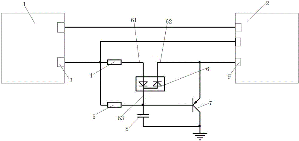
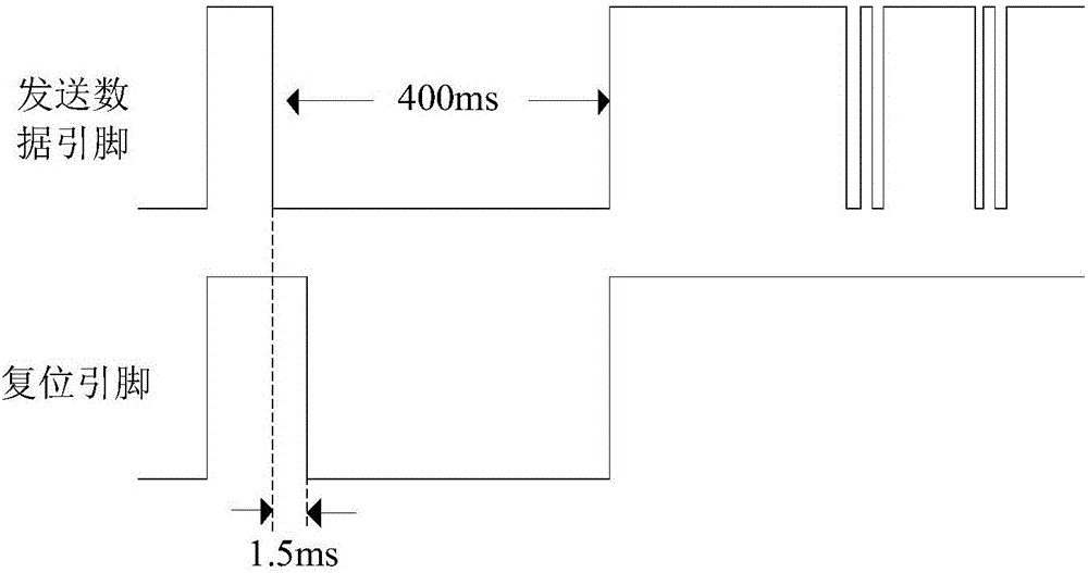
[0020] Such as Figure 1-2 As shown, a circuit that uses serial communication to control CPU reset includes a first resistor 4 and a second resistor 5 connected in parallel to the send data pin (TXD) 3 of the host computer 1, and the other end of the first resistor 4 is connected to The first pin 61 of the double diode 6, the other end of the second resistor 5 is connected to the third pin 63 of the double diode 6 and the base of the PNP transistor 7, the second pin 62 of the double diode 6 is connected to the PNP transistor The emitter of 7 is connected and connected to the reset pin (nRESET) 9 of CPU2, the base of PNP transistor 7 is connected with first capacitor 8, and the other end of first capacitor 8 is connected with the collector of PNP transistor 7 and grounded.
[0021] After power-on, the upper computer 1 sends...
PUM
 Abstract
Description
Claims
Application Information