Point distribution method and system of reactive power compensation device in multi-infeed system

A compensation device and multi-infeed technology, applied in reactive power compensation, reactive power adjustment/elimination/compensation, etc., can solve problems such as power supply system instability, secondary commutation failure between stations, commutation failure, etc. Maximize economic benefits and optimize coupling relationship

Active Publication Date: 2017-06-13
XJ ELECTRIC +3
View PDF2 Cites 5 Cited by
  • Summary
  • Abstract
  • Description
  • Claims
  • Application Information

AI Technical Summary

Problems solved by technology

However, when the power grid in the multi-infeed DC area is weak and the electrical coupling relationship between the multi-infeed points is strong, (continuous) commutation failures and secondary commutation failures between stations are prone to occur, resulting in instability of the power supply system , which has seriously affected the healthy and rapid economic development of the receiving regions

Method used


Image

  • Point distribution method and system of reactive power compensation device in multi-infeed system
  • Point distribution method and system of reactive power compensation device in multi-infeed system
  • Point distribution method and system of reactive power compensation device in multi-infeed system

Examples


Embodiment Construction

[0042] The specific embodiments of the present invention will be further described below in conjunction with the drawings.

[0043] The embodiment of the method for distributing the reactive power compensation device in the multi-feed-in system of the present invention

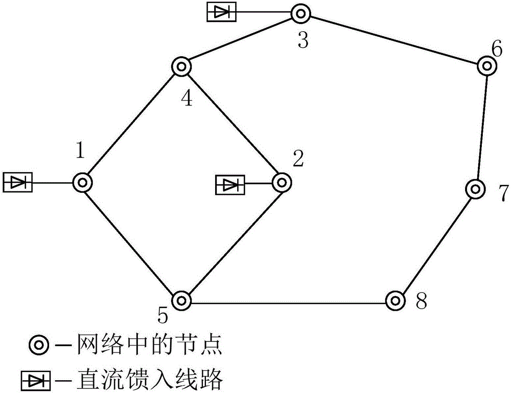
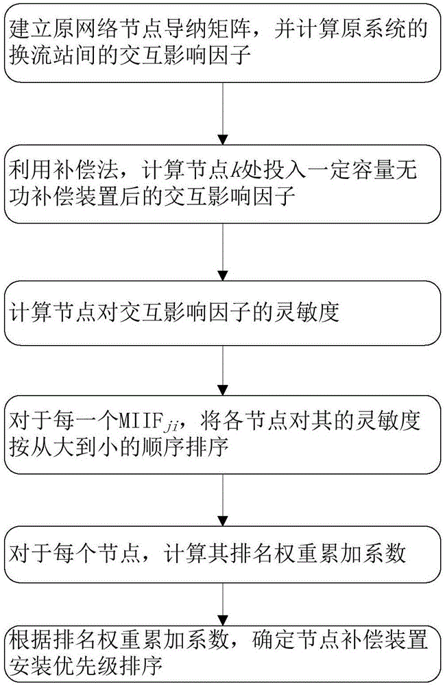
[0044] The present invention first calculates the sensitivity of the node, and then the sensitivity of each node in the AC grid that is fed into the receiving end of the DC system is cumulatively sorted according to a certain weight. The higher the ranking, the lower the commutation value when the reactive power compensation device is installed here. The coupling effect between stations is the most obvious, the system performance can be improved the most, and the economic benefits can be maximized. Therefore, using the ranking as the priority of the reactive power compensation device can minimize the interaction impact between the converter stations. The process of the method is as follows figure 2 As shown, the ...


PUM


Abstract

The invention relates to a point distribution method and system of a reactive power compensation device in a multi-infeed system, and belongs to the technical field of high-voltage direct current transmission. According to the interaction effect factors between every two converter stations before and after the reactive power compensation device is added, the sensitivity of each node to the converter station interaction effect factors is calculated, the sensitivity of all the nodes to the interaction effect factors is ranked, and therefore the priority of installation positions of the reactive power compensation device is determined. According to the method and the system, the sensitivity of the nodes is made use of for point distribution of the reactive power compensation device, the influence of an alternating current side network structure on the current commutating bus interaction effect factor is considered, the influence of the compensation characteristic of the reactive power compensation device on the current commutating bus interaction effect is also considered, and therefore the coupling relationship between every two current commutating buses is optimally improved in the whole.

Description

Technical field [0001] The invention relates to a method and a system for arranging reactive power compensation devices in a multi-feed system, and belongs to the technical field of high-voltage direct current transmission. Background technique [0002] East China and South China are the two regions with the largest demand for electricity in the country, and they are also the location of multiple DC transmission lines, which also makes these two regions have formed a multi-feed DC transmission pattern. In the future, with the further development of the economy, the construction of more conventional UHV DC transmission lines and the multi-feed DC transmission pattern will become the new normal. However, when the power grid in the multi-infeed DC area is weak and the electrical coupling relationship between the multi-infeed points is strong, (continuous) commutation failures and secondary commutation failures between stations are prone to occur, resulting in unstable power supply s...

Claims


Application Information

Patent Timeline
Patent Type & Authority Applications(China)
IPC IPC(8): H02J3/18
CPCY02E40/30H02J3/18
Inventor 胡丁文王先为吴金龙张军刘欣和冯宇鹏李道洋马焕
Owner XJ ELECTRIC
Why Eureka
Try Eureka