
Locking device

A locking and slotting technology, which is applied in metal processing, metal processing equipment, manufacturing tools, etc., can solve the problems of easy sliding and loosening, elastic gasket leakage, etc., and achieve the effect of convenient locking and wide application range

Inactive Publication Date: 2017-06-20
AU OPTRONICS (XIAMEN) CORP +1
View PDF5 Cites 0 Cited by
  • Summary
  • Abstract
  • Description
  • Claims
  • Application Information

AI Technical Summary

Problems solved by technology

[0002] As a fastener, the most important performance of the screw is its anti-vibration or anti-loosening performance. When an ordinary screw is locked, its thread and the thread of the locked part are in parallel contact, and it is easy to slide and loosen during vibration. take off
[0003] In order to solve the problem of loosening, the usual method is to use anti-falling screws or add elastic washers, but since the adhesive resin of the anti-falling screws is locked and then taken out, there will be chipping problems, and the elastic washers will be missed. risk, so many methods in the prior art have more or less certain problems in improving the problem of loosening

Method used


Image

  • Locking device
  • Locking device
  • Locking device

Examples


Embodiment Construction

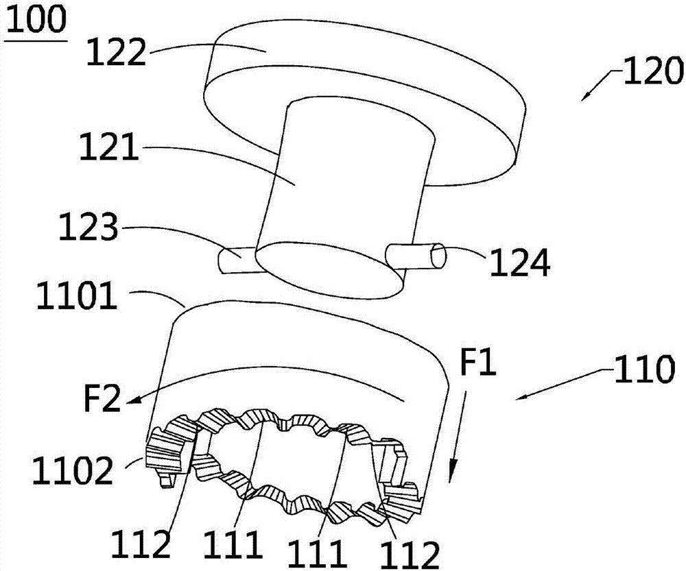
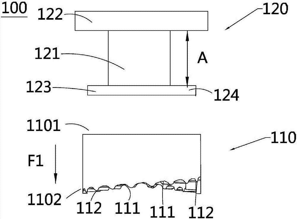
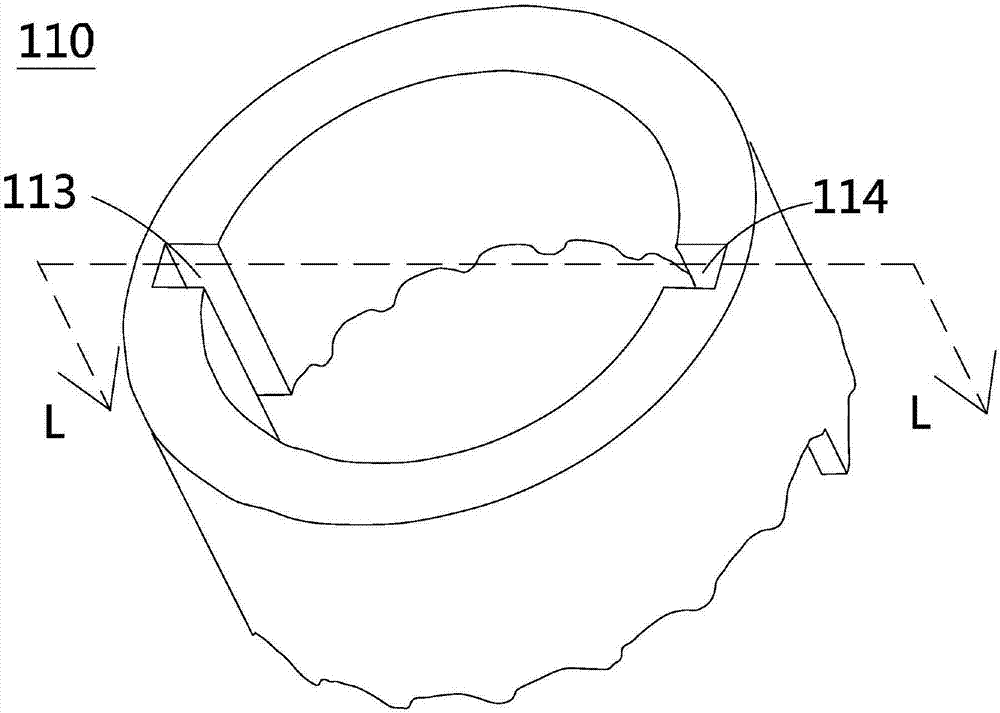
[0027] figure 1 It is an exploded view of the locking device of the present invention, figure 2 It is an exploded view of another perspective of the locking device of the present invention, image 3 for figure 1 A schematic diagram of another viewing angle of the first locking unit in Figure 4 for image 3 The schematic cross-sectional view of the first locking unit along the LL line. Please also refer to Figure 1 to Figure 4 , the locking device 100 is used for locking components, and includes a first locking unit 110 and a second locking unit 120 .

[0028] The first locking unit 110 has a through hole and has an opposite first end 1101 and a second end 1102, the penetration direction of the through hole is directed from the first end 1101 to the second end 1102, that is, the first locking unit 110 is ring-shaped, The first card slot group 101 is arranged around the second end 1102. The first card slot group 101 is composed of N card slots 111 and N+1 bumps 112 arra...


PUM


Abstract

The invention relates to a locking device. The locking device comprises a first locking unit and a second locking unit. The first locking unit is provided with a through hole, a first end and a second end, and the first end and the second end are opposite to each other; the second end is provided with a first clamping groove set which is arranged around the second end; the first clamping groove set is composed of N+1 convex points and N clamping grooves, and the N+1 convex points and the N clamping grooves are alternately arranged in sequence; the opening directions of the N clamping grooves are all the first direction; every two of the N clamping grooves are connected through the corresponding convex point of the N+1 convex points; the inner wall of the first locking unit is provided with a first groove from the first end to the second end; the second locking unit is provided with a cylindrical body, a cap body and a first protrusion; when the second locking unit is arranged on the first locking unit in a sleeved manner through the through hole, the first protrusion reaches the second end through the first groove from the first end; and in the second direction, from the position of the first groove, the distances of the N clamping grooves in the first clamping groove set away from the first end are sequentially increased, and the second locking unit is rotated to make the first protrusion locked by one clamping groove in the first clamping groove set.

Description

technical field [0001] The invention relates to a locking device, in particular to an anti-loosening locking device. Background technique [0002] As a fastener, the most important performance of the screw is its anti-vibration or anti-loosening performance. When an ordinary screw is locked, its thread and the thread of the locked part are in parallel contact, and it is easy to slide and loosen during vibration. take off. [0003] In order to solve the problem of loosening, the usual method is to use anti-falling screws or add elastic washers, but since the adhesive resin of the anti-falling screws is locked and then taken out, there will be chipping problems, and the elastic washers will be missed. risk, so many methods in the prior art have more or less certain problems in improving the problem of loosening. Contents of the invention [0004] In order to improve the above problem of anti-loosening, the present invention provides a locking device. [0005] The above-me...

Claims


Application Information

Patent Timeline
Patent Type & Authority Applications(China)
IPC IPC(8): B23P19/06
CPCB23P19/06
Inventor 陈燕青叶婷婷王雅涛
Owner AU OPTRONICS (XIAMEN) CORP
Learn More