A dynamic correction mechanism with screw lock

A dynamic correction and screw technology, applied in metal processing, metal processing equipment, manufacturing tools, etc., can solve the problems of reduced success rate of electric batch lock screws, defective products, and increased production costs, so as to improve work efficiency and reduce defective rates. , the effect of improving work efficiency

Active Publication Date: 2017-02-22
BOZHON PRECISION IND TECH CO LTD
View PDF7 Cites 0 Cited by
  • Summary
  • Abstract
  • Description
  • Claims
  • Application Information

AI Technical Summary

Problems solved by technology

[0004] Generally, after the electric screwdriver absorbs the screw, it directly locks the screw into the product, and does not correct the position of the screw. In this way, there will be defective products when locking, and the success rate of the electric screwdriver to lock the screw will be reduced, thereby increasing production. cost

Method used


Image

  • A dynamic correction mechanism with screw lock
  • A dynamic correction mechanism with screw lock
  • A dynamic correction mechanism with screw lock

Examples


Embodiment Construction

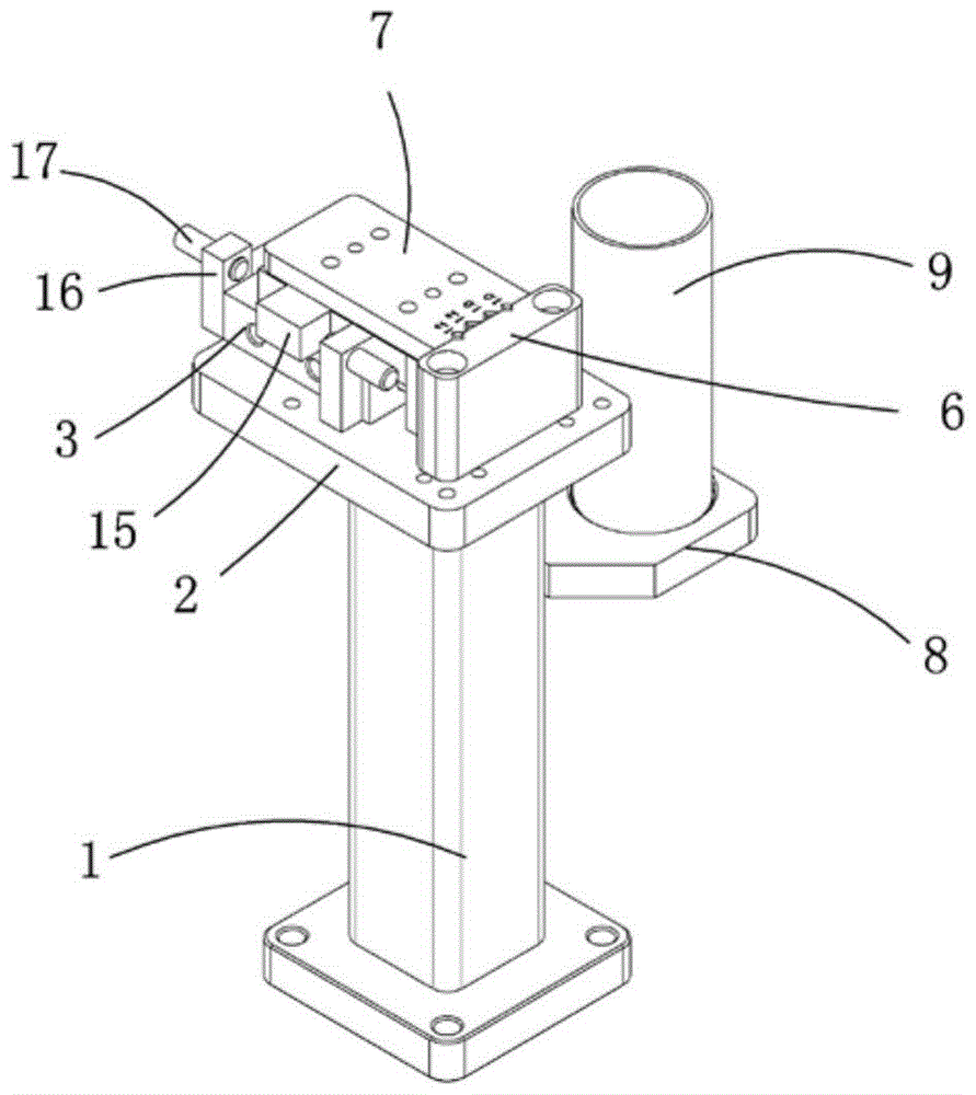
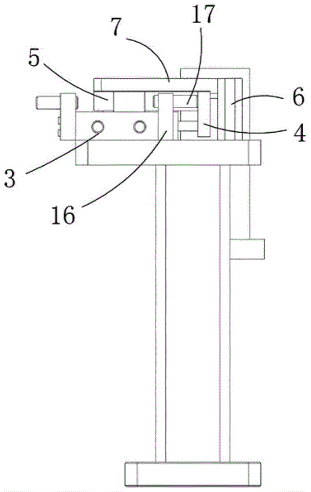
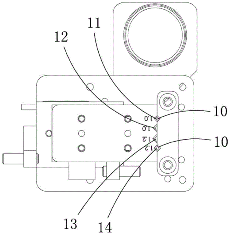
[0024] Examples, see attached Figure 1~4 , a dynamic correction mechanism with a screw lock, which includes a corrector base 1, a cylinder fixed plate 2, a cylinder 3, a push plate 4, a moving plate 5, a correction block a6, a dynamic correction block 7, a magnet fixed plate 8 and a waste bucket 9 , the cylinder fixed plate is installed on the base of the corrector; the cylinder is installed on the left side of the upper part of the cylinder fixed plate, the front end of the piston rod of the cylinder is connected with the push plate, and the push plate is fixedly connected with the moving plate, and the moving plate is located at Above the cylinder, driven by the cylinder, the push plate can drive the moving plate to move; a magnet fixing plate is installed on the back of the corrector base, and a groove is arranged on the magnet fixing plate, and a magnet is placed in the groove, and the waste barrel is adsorbed on the magnet. Its adsorption is stable and reliable, and it i...


PUM


Abstract

The invention relates to a dynamic correction mechanism for screw lock. A cylinder is mounted on a corrector base through a cylinder fixing plate; a push plate is connected to the front end of the cylinder and is fixedly connected with a moving plate; a correction block a is fixedly mounted at the upper part of the right side of the cylinder fixing plate; a dynamic correction block is mounted on the moving plate; two stepped holes are formed in the left side wall of the correction block a; stepped holes a, b, c and d are formed in the right side wall of the dynamic correction block; the stepped holes a and d and the two stepped holes in the correction block a are symmetrical correspondingly and are of the same structure; the cylinder drives the dynamic correction block to be fitted with the left side face of the correction block a; after the stepped holes a and d are symmetrical to the two stepped holes on the correction block a correspondingly, a correction screw can be screwed; or, when the dynamic correction block moves, one side face of a screw in the stepped holes b and c can be fitted with the left side face of the correction block a to fit with the correction screw, so that the success rate of locking the screw by an electric screwdriver is improved.

Description

[0001] Technical field: [0002] The invention relates to the field of correction mechanism equipment, and more specifically relates to a dynamic correction mechanism with a screw lock. [0003] Background technique: [0004] Generally, after the electric screwdriver absorbs the screw, it directly locks the screw into the product, and does not correct the position of the screw. In this way, there will be defective products when locking, and the success rate of the electric screwdriver to lock the screw will be reduced, thereby increasing production. cost. Therefore, it is necessary to design a mechanism that guides the position of the screw after the electric screwdriver sucks the screw, which can increase the success rate of the electric screwdriver locking the screw, thereby improving the work efficiency of screw locking in the assembly work and reducing the labor of the operator. strength and reduce production costs. [0005] Invention content: [0006] The purpose of the...

Claims


Application Information

Patent Timeline
Patent Type & Authority Patents(China)
IPC IPC(8): B23P19/10
CPCB23P19/06B23P19/107
Inventor 吕绍林汪炉生唐为付史豪尊
Owner BOZHON PRECISION IND TECH CO LTD
Why Eureka
Try Eureka