
Constant volume valve

A technology of constant volume and valve seat, which is applied to lift valves, valve devices, mechanical equipment, etc., can solve the problems of difficult cleaning and sterilization, complex structure of plunger valves, and inappropriate aseptic filling, etc. The effect of aseptic filling

Pending Publication Date: 2017-06-23
JIANGSU NEWAMSTAR PACKAGING MACHINERY
View PDF6 Cites 5 Cited by
  • Summary
  • Abstract
  • Description
  • Claims
  • Application Information

AI Technical Summary

Problems solved by technology

However, the plunger valve itself has a complex structure, is not easy to clean and sterilize, and is not suitable for aseptic filling.

Method used


Image

  • Constant volume valve
  • Constant volume valve
  • Constant volume valve

Examples


Embodiment Construction

[0022] The technical solutions of the present invention will be further elaborated below in conjunction with the accompanying drawings.

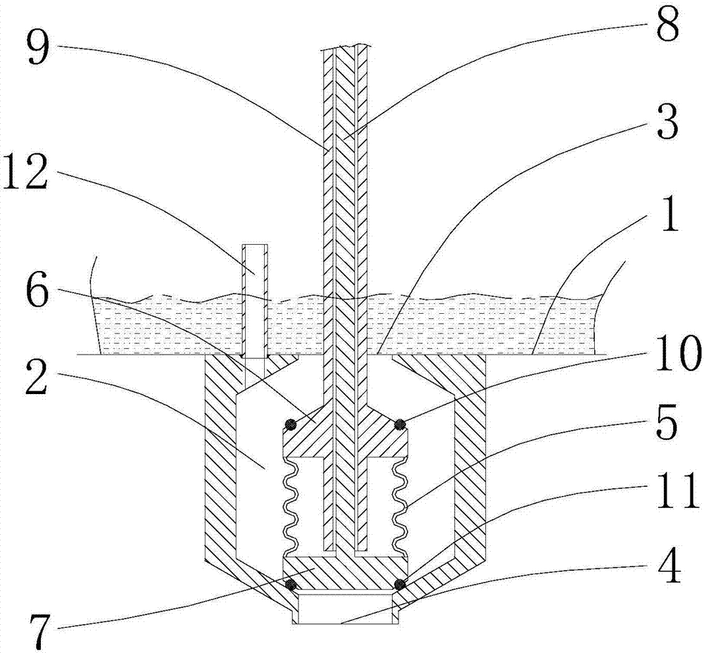
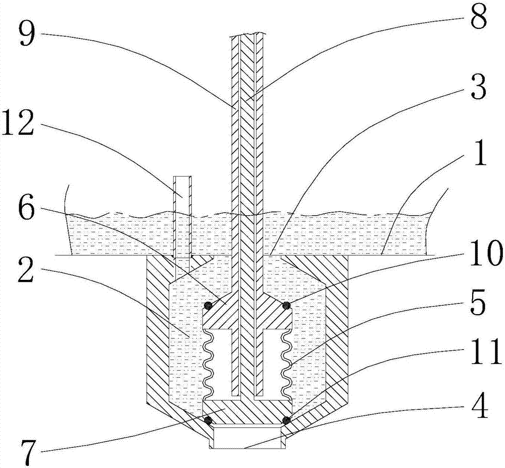
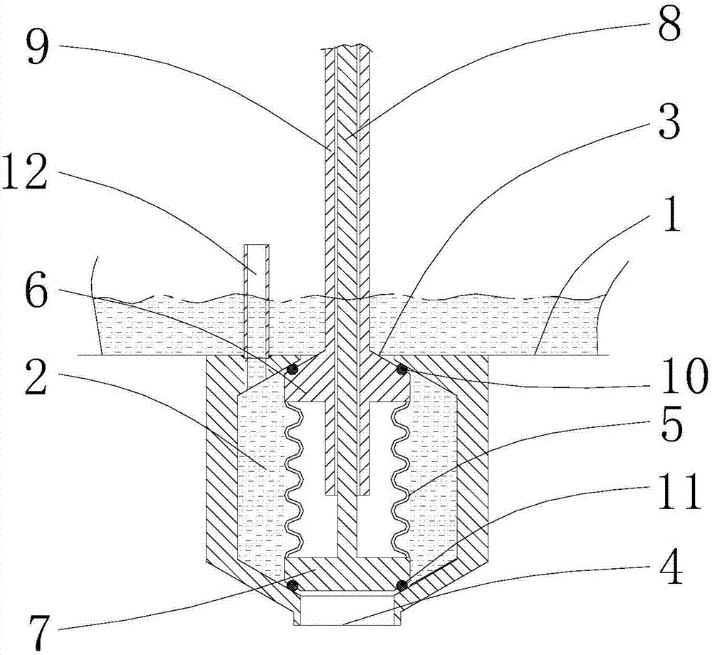
[0023] see figure 1 As shown, the above-mentioned constant volume valve is communicated with a storage tank 1 for storing materials. In this embodiment, the constant volume valve is used for precise volume determination and aseptic filling of pulp beverages.

[0024] The constant volume valve includes a valve cavity 2 , a feed port 3 opened on the valve cavity 2 and communicated with the storage tank 1 , and a discharge port 4 opened on the valve cavity 2 . In this embodiment, the valve cavity 2 is located below the storage tank 1 , and the connecting line between the center of the feed port 3 and the center of the discharge port 4 is distributed along the vertical direction

[0025] The constant volume valve also includes an elastic member 5 extending and extending along its own length and extending between the feeding port 3 and the disch...


PUM


Abstract

The invention discloses a constant volume valve which communicates with a storage tank used for storing materials. The constant volume valve comprises a valve cavity, a feeding port, a discharging port, elastic parts, a first valve seat, a second valve seat, a first driving mechanism and a second driving mechanism, wherein the feeding port is formed in the valve cavity and communicates with the storage tank, the discharging port is formed in the valve cavity, the elastic parts are arranged between the feeding port and the discharging port and extend and contract in the extending direction of the length of the elastic parts, the first valve seat is arranged at the ends, close to the feeding port, of the elastic parts, the second valve seat is arranged at the ends, close to the discharging port, of the elastic parts, the first driving mechanism is used for driving the first valve seat to move along the elastic extension and contraction direction of the elastic parts to plug or get far away from the feeding port, and the second driving mechanism is used for driving the second valve seat to move along the elastic extension and contraction direction of the elastic parts to plug or get away from the discharging port. According to the constant volume valve, the elastic parts are arranged between the feeding port and the discharging port, the first valve seat and the second valve seat are arranged on the two ends of the elastic parts, the first driving mechanism and the second driving mechanism are arranged to be used for driving the first valve seat and the second valve seat respectively, and therefore the precise volume fixing and the sterile filling of the materials are realized.

Description

technical field [0001] The invention relates to the technical field of filling, in particular to a constant volume valve used for constant volume filling of fruit pulp beverages. Background technique [0002] In the filling of pulp beverages, because the pulp particles themselves have a certain shape and volume, in order to accurately measure and fill the pulp particles, a plunger valve is generally used to fill the pulp at a constant volume. However, the plunger valve itself has a complex structure, which is not easy to clean and sterilize, nor is it suitable for aseptic filling. SUMMARY OF THE INVENTION [0003] The purpose of the present invention is to provide a constant volume valve, which can accurately measure and fill materials, has a simple structure, and is easy to clean and sterilize. [0004] To achieve the above object, the technical scheme adopted in the present invention is: [0005] A constant volume valve communicates with a storage tank for storing mate...

Claims


Application Information

Patent Timeline
IPC IPC(8): F16K1/36F16K1/32F16K1/44
CPCF16K1/32F16K1/36F16K1/44
Inventor 刘波杨亚军张国宏
Owner JIANGSU NEWAMSTAR PACKAGING MACHINERY
Learn More