
Safety power connection device

A joint device and power safety technology, which is applied to coupling devices, parts of connecting devices, devices to prevent contact with live contacts, etc. Simple operation and the effect of improving the safety of electricity consumption

Active Publication Date: 2017-06-23
ANHUI LIXIN RUBBER TECH CO LTD
View PDF4 Cites 70 Cited by
  • Summary
  • Abstract
  • Description
  • Claims
  • Application Information

AI Technical Summary

Problems solved by technology

[0002] Household appliances, industrial equipment and other electrical equipment need to be energized before they can operate and operate, and these electrical equipment need to be connected with a plug and socket to be energized. In traditional sockets, in order to facilitate power on and off, the plug is generally inserted into the The socket can be powered on. Although the traditional socket and plug are more convenient to use, if someone inserts a metal rod or sheet metal into the socket with bare hands, the electricity will be conducted to the human body, which will cause an electric shock accident. Therefore, it will have a great impact on the equipment, and more seriously, it will cause great harm to the human body, so there is a great potential safety hazard in the traditional socket

Method used


Image

  • Safety power connection device
  • Safety power connection device
  • Safety power connection device

Examples


Embodiment Construction

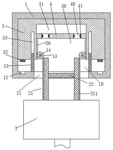
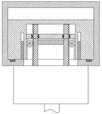
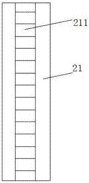
[0014] Combine below Figure 1-3 The present invention will be described in detail.

[0015] refer to Figure 1-3 , according to an embodiment of the present invention, an electric safety joint device includes a fixed base 1 fixed in the wall and a power connector 2 connected to electrical equipment, the fixed base 1 is provided with a sliding cavity 10, so A slot 11 communicating with the outside world is provided in the front wall of the sliding chamber 10, a sliding frame 3 that can slide back and forth is installed in the sliding chamber 10, and the sliding frame 3 is provided with an access groove 30 that opens toward the front end and penetrates up and down. The left and right sides of the sliding frame 3 are symmetrically provided with narrow and long slots 33 with openings facing the front end, the rear side of the front end wall of the sliding chamber 10 is fixed with a shielding plate 13 symmetrically, and the shielding plate 13 extends into the In the elongated gr...


PUM


Abstract

A safety power connection device comprises a fixed base fixed to the wall and a power connector connected to electrical equipment. The fixed base has a slide cavity inside. A slot communicated with the outside is arranged in the front end wall of the slide cavity. A slide frame capable of sliding back and forth is installed in the slide cavity. The slide frame is provided with an access slot which has an opening facing the front end and is through up and down. Long and narrow slots with openings facing the front end are symmetrically arranged on the left and right sides inside the slide frame. Shielding plates are fixedly arranged on the rear side of the front end wall of the slide chamber in bilateral symmetry. Power supply slots are arranged in the rear side of the front end wall of the slide chamber in bilateral symmetry. Conductive heads matching the power supply slots are arranged at the front end of the slide frame in bilateral symmetry. Driven racks are arranged on the two sidewalls of the access slot. Gears meshed with the driven racks are installed in bilateral symmetry in the slide cavity through a rotating shaft. A transverse plate is fixedly installed in the access slot. Through slots are arranged in bilateral symmetry in the transverse plate. Conductive elastic pieces are installed in the through slots.

Description

technical field [0001] The invention relates to the field of electric power utilization and power supply, in particular to an electric safety joint device. Background technique [0002] Household appliances, industrial equipment and other electrical equipment need to be powered on before they can operate and operate, and these electrical equipment need to be connected to a plug and socket to be powered on. In traditional sockets, in order to facilitate power on and off, the plug is generally inserted into the The socket can be powered on. Although the traditional socket and plug are more convenient to use, if someone uses a metal rod or sheet metal to insert into the socket with bare hands, the electricity will be conducted to the human body, which will cause an electric shock accident. Therefore, it will have a great impact on the equipment, and more seriously, it will cause great harm to the human body, so there is a great potential safety hazard in the traditional socket....

Claims


Application Information

Patent Timeline
IPC IPC(8): H01R13/44H01R13/187H01R13/04H01R13/629
CPCH01R13/04H01R13/187H01R13/447H01R13/629
Inventor 戎传龙
Owner ANHUI LIXIN RUBBER TECH CO LTD
Learn More