Connector for frame sash structure

A frame fan and fan rod technology, which is applied in the protection field of building windows, can solve the problems of affecting the service life, the self-weight drop and looseness of the window sash, etc., and achieve the effect of improving the convenience of installation, simple and compact structure, and improving the service life

Active Publication Date: 2017-06-30
HUNAN GOLDWELL NEW MATERIALS TECH CO LTD
View PDF5 Cites 0 Cited by
  • Summary
  • Abstract
  • Description
  • Claims
  • Application Information

AI Technical Summary

Problems solved by technology

Because the window sash itself has a certain weight, after repeated opening and closing and long-term opening, the window sash will fall to a certain extent due to its own weight, making it difficult to close the window sash, and in severe cases, the window sash and window frame will be scratched and worn, which will affect its service life; Using additional mortise lock parts, the operation is complicated, especially when it involves batch installation, which seriously affects the installation efficiency; in addition, due to the need for precise positioning during on-site installation, it is found in practice that the slots of window frames and sash often appear. The installation deviation makes subsequent locking very difficult, and most of the slots of the window frame and sash are installed by screws, which often appear loose

Method used


Image

  • Connector for frame sash structure
  • Connector for frame sash structure
  • Connector for frame sash structure

Examples


Embodiment 1

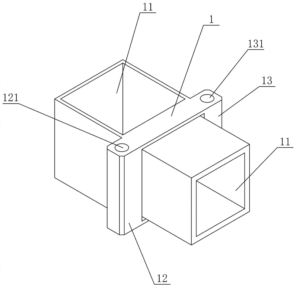
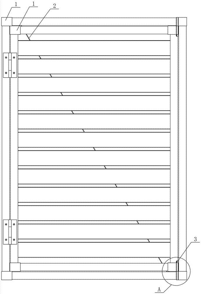
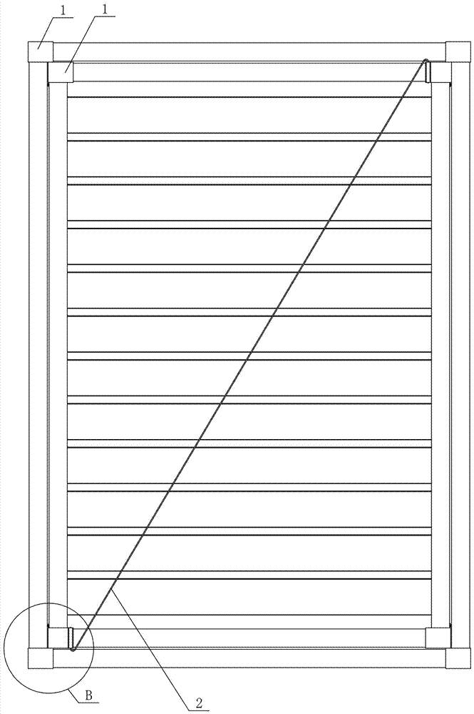
[0059] Figure 1 to Figure 5It shows the first embodiment of the joint used in the frame fan structure of the present invention, the joint used in the frame fan structure includes a joint body 1, and the joint body 1 is provided with at least two connections for connecting the frame fan rods part 11, the joint body 1 is also provided with a pull-joint part 12 and a plug-in part 13, the pull-joint part 12 is provided with a cable 2, and the plug-in part 13 is provided with a latch 3. In this structure, the ends of adjacent frame horizontal bars and frame vertical bars are connected and enclosed by the joint body 1 to form a frame structure, and the ends of adjacent fan horizontal bars and fan vertical bars are connected and enclosed by joint bodies 1 to form a fan frame structure. Frame structure, compared with the traditional built-in connection hinge, the joint body 1 is externally installed on the end of the rod, so that it is convenient to form the pull-joint part 12 and th...

Embodiment 2

[0068] Figure 6 to Figure 10 Shows the second embodiment of the joint used in the frame-sash structure of the present invention, the joint used in the frame-sash structure is basically the same as that of Embodiment 1, the difference is that in this embodiment, the pull joint hole 121 is set as a threaded hole , Both ends of the cable 2 are provided with tension bolts 21, and the tension bolts 21 are threadedly connected with the threaded holes at the corresponding ends. In this structure, by setting the tension connection hole 121 as a threaded hole, and setting tension bolts 21 at both ends of the drag cable 2, the tension installation can be completed only by tightening the tension bolts 21 at both ends, so that the tension can be obtained. It is controllable and also improves the convenience of installation.

[0069] In this embodiment, there is one pull connection portion 12 , and the pull connection hole 121 is vertically arranged and located at the outer edge of the j...

Embodiment 3

[0071] Figure 11 to Figure 15 It shows the third embodiment of the joint used in the frame-sash structure of the present invention, the joint used in the frame-sash structure is basically the same as that of Embodiment 2, the only difference is that in this embodiment, the pull-joint part 12 is provided with One, the pull connection hole 121 is arranged horizontally and is located at the outer edge of the joint body 1 . This arrangement makes the fan body indirectly receive the upward vertical component force of the connecting portion 12 while being subjected to the main force of the oblique pull of the cable 2, which greatly improves the tension strength.

[0072] In this embodiment, there is one socket part 13, and the socket hole 131 is arranged horizontally. Such setting means that the insertion part 13 is arranged horizontally, and the latch 3 can be inserted horizontally to complete the locking.


PUM


Abstract

The invention discloses a connector for a frame sash structure. The connector comprises a connector body, at least two connecting parts for being connected with a frame sash rod are arranged on the connector body, a pull joint part and an inserting joint part are further arranged on the connector body, an inhaul cable is arranged on the pull joint part in a matched mode, and a plug pin is arranged on the inserting joint part in a matched mode. The connector for the frame sash structure has the advantages of being simple and compact in structure, convenient to mount, long in service life, high in mounting precision and stable and reliable in locking and tightening.

Description

technical field [0001] The invention mainly relates to the protection technology of building windows, in particular to a joint for frame-sash structures. Background technique [0002] Along with the continuous development of the entire social economy and the continuous improvement of living conditions, how to have a comfortable, safe and good rest and sleep environment is a problem that people are very concerned about. [0003] Existing window guards, blinds, etc. can basically achieve the effects of preventing children from falling from the window, preventing theft, and ensuring privacy. In the prior art, the window sash is generally hinged with the window frame to form an opening and closing structure, and then a mortise lock component is installed on the window frame and the window sash to ensure the locking function when the protective window is closed. Because the window sash itself has a certain weight, after repeated opening and closing and long-term opening, the win...

Claims


Application Information

Patent Timeline
Patent Type & Authority Applications(China)
IPC IPC(8): E06B3/968
CPCE06B3/968
Inventor 谢斌泉其他发明人请求不公开姓名
Owner HUNAN GOLDWELL NEW MATERIALS TECH CO LTD
Why Eureka
Try Eureka