Joints for frame-leaf construction
A frame fan and fan rod technology, which is applied in the protection field of building windows, can solve the problems of affecting the service life, the weight of the window sash falling, loosening, etc., and achieve the effect of improving the convenience of installation, simple and compact structure, and preventing scratches and wear
- Summary
- Abstract
- Description
- Claims
- Application Information
AI Technical Summary
Problems solved by technology
Method used
Image
Examples
Embodiment 1
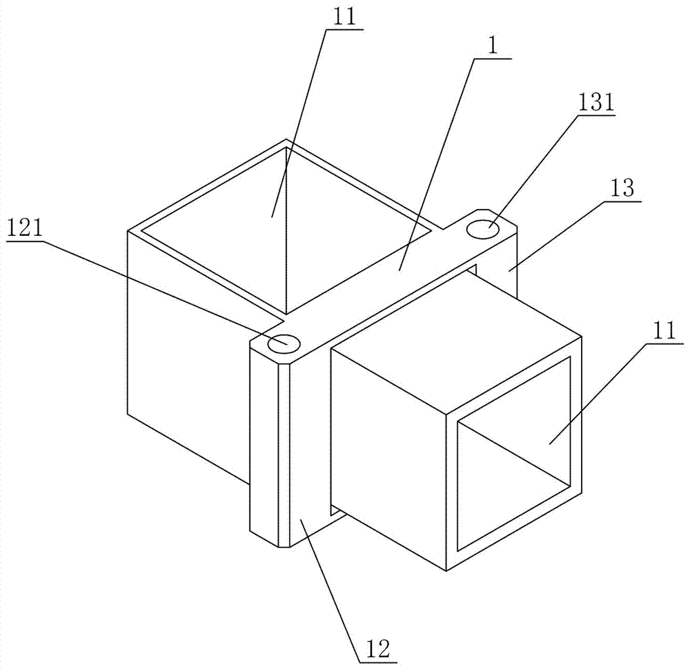
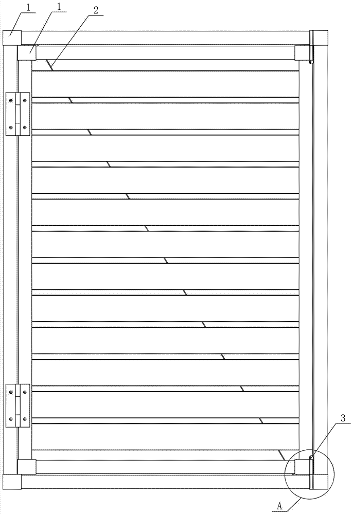
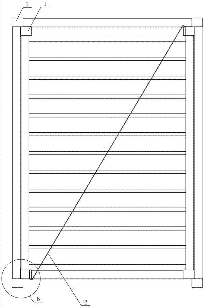
[0059] Figure 1 to Figure 5It shows the first embodiment of the joint used in the frame fan structure of the present invention, the joint used in the frame fan structure includes a joint body 1, and the joint body 1 is provided with at least two connections for connecting the frame fan rods part 11, the joint body 1 is also provided with a pull-joint part 12 and a plug-in part 13, the pull-joint part 12 is provided with a cable 2, and the plug-in part 13 is provided with a latch 3. In this structure, the ends of adjacent frame horizontal bars and frame vertical bars are connected and enclosed by the joint body 1 to form a frame structure, and the ends of adjacent fan horizontal bars and fan vertical bars are connected and enclosed by joint bodies 1 to form a fan frame structure. Frame structure, compared with the traditional built-in connection hinge, the joint body 1 is externally installed on the end of the rod, so that it is convenient to form the pull-joint part 12 and th...
Embodiment 2
[0068] Figure 6 to Figure 10 Shows the second embodiment of the joint used in the frame-sash structure of the present invention, the joint used in the frame-sash structure is basically the same as that of Embodiment 1, the difference is that in this embodiment, the pull joint hole 121 is set as a threaded hole , Both ends of the cable 2 are provided with tension bolts 21, and the tension bolts 21 are threadedly connected with the threaded holes at the corresponding ends. In this structure, by setting the tension connection hole 121 as a threaded hole, and setting tension bolts 21 at both ends of the drag cable 2, the tension installation can be completed only by tightening the tension bolts 21 at both ends, so that the tension can be obtained. It is controllable and also improves the convenience of installation.
[0069] In this embodiment, there is one pull connection portion 12 , and the pull connection hole 121 is vertically arranged and located at the outer edge of the j...
Embodiment 3
[0071] Figure 11 to Figure 15 It shows the third embodiment of the joint used in the frame-sash structure of the present invention, the joint used in the frame-sash structure is basically the same as that of Embodiment 2, the only difference is that in this embodiment, the pull-joint part 12 is provided with One, the pull connection hole 121 is arranged horizontally and is located at the outer edge of the joint body 1 . This arrangement makes the fan body indirectly receive the upward vertical component force of the connecting portion 12 while being subjected to the main force of the oblique pull of the cable 2, which greatly improves the tension strength.
[0072] In this embodiment, there is one socket part 13, and the socket hole 131 is arranged horizontally. Such setting means that the insertion part 13 is arranged horizontally, and the latch 3 can be inserted horizontally to complete the locking.
PUM
 Abstract
Description
Claims
Application Information
 - R&D
- Intellectual Property
- Life Sciences
- Materials
- Tech Scout
- Unparalleled Data Quality
- Higher Quality Content
- 60% Fewer Hallucinations
Browse by: Latest US Patents, China's latest patents, Technical Efficacy Thesaurus, Application Domain, Technology Topic, Popular Technical Reports.
© 2025 PatSnap. All rights reserved.Legal|Privacy policy|Modern Slavery Act Transparency Statement|Sitemap|About US| Contact US: help@patsnap.com


