Shell component having hydraulic pressure line

A component and circuit technology, applied in the field of shell components, can solve the problems of time-intensive, complicated technology, and cost-intensive, and achieve the effect of avoiding leakage and supplementary processing.

Active Publication Date: 2017-07-04
ROBERT BOSCH GMBH
View PDF8 Cites 0 Cited by
  • Summary
  • Abstract
  • Description
  • Claims
  • Application Information

AI Technical Summary

Problems solved by technology

Such production of hydraulic blocks or housing components with line sections of hydraulic lines is technically complex and thus also time-intensive and cost-intensive

Method used


Image

  • Shell component having hydraulic pressure line
  • Shell component having hydraulic pressure line
  • Shell component having hydraulic pressure line

Examples


Embodiment Construction

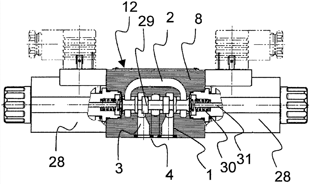
[0051] figure 1 A magnetically actuatable directional slide valve is shown by way of example for a number of other components, which may have line sections of hydraulic lines. The directional control slide valve is provided with a housing part 12 which is formed from a solid body 8 in the manner suggested here. A (possibly branched) hydraulic line 2 is formed in this housing component 12 . The hydraulic lines 2 shown here protrude from the solid body 8 at two points on the housing component 12 . There, a line section 1 is formed in each case, which has a channel 3 and a delimited sealing surface 4 surrounding said channel 3 and a space.

[0052] For the sake of illustration, the mode of operation of the magnetically actuatable directional slide valve should be briefly shown. Arranged on the sides of the housing component 12 are two magnets 28 by means of which a control slide 29 arranged centrally in the housing component 12 can be moved. The control slide 29 is moved on b...


PUM


Abstract

A shell component (12) having a hydraulic pressure line is provided and comprises at least one line section (1) of a hydraulic pressure line (2) having at least one channel (3) and a sealing surface (4) limiting the channel (3) on the space, a surface contour feature (19) is formed on the sealing surface and has at least one annual projection around the channel (3).

Description

technical field [0001] The invention relates to a housing component having a line section of a hydraulic line which has at least one channel and a sealing surface which surrounds and spatially delimits the channel. The invention finds particular application in hydraulic blocks which are used for conveying fluids, in particular oil, under high pressure. Background technique [0002] The invention finds particular application in hydraulic blocks which are used for conveying fluids, in particular oil, under high pressure. The invention is used in particular in valve housing blocks or valves, which previously had a housing made of a metallic cast material. The valves are usually screwed to the control block and are connected at the connection surface to hydraulic lines formed in the control block. The fluid channel then joins into the coupling face of the valve. The junction is surrounded by an annular groove, into which an elastic sealing ring (in particular for axial sealin...

Claims


Application Information

Patent Timeline
IPC IPC(8): F16J15/06F16K27/04
CPCF16J15/06F16K27/04F16J15/062F16K27/00
Inventor S·布勒德纳A·京德J·L·比罗德
Owner ROBERT BOSCH GMBH
Why Eureka
Try Eureka