A tool for removing shouldered bushing of drilling jig and its use method

A technology for removing tools and bushings, which is applied in the direction of drilling molds for workpieces, manufacturing tools, hand-held tools, etc., can solve the problems of insufficient space, affecting the production progress of parts, damage, etc., and achieve the effect of improving replacement efficiency

Active Publication Date: 2019-03-05
SHENYANG AIRCRAFT CORP
View PDF5 Cites 0 Cited by
  • Summary
  • Abstract
  • Description
  • Claims
  • Application Information

AI Technical Summary

Problems solved by technology

[0002] The bushing used to process the hole of the part on the drilling jig will wear out after long-term use, resulting in an out-of-tolerance hole diameter, so that the drilling jig cannot meet the production demand
Therefore, it is often necessary to replace the worn bush. Since the relative distance between the drill template and the main body is relatively close, the operable space during the removal process is small. For the shoulderless bush, it can be used from the side with a large operating space through a small cylindrical pin. The bushing is removed by hammering, and the bushing with a shoulder must be removed from the side without the shoulder, and the maneuverable space in this direction is very small, and the method of hammering is often due to insufficient space. , the direction is not easy to grasp, resulting in the destruction of the bottom hole of the drill formwork bush during the bushing removal process, so it is necessary to re-expand the bottom hole of the drill formwork bush to meet the relative position requirements of this position
After repeated several times, the drill template needs to be remanufactured if there is no processing space, which causes a great waste of production and affects the production progress of the corresponding parts

Method used


Image

  • A tool for removing shouldered bushing of drilling jig and its use method
  • A tool for removing shouldered bushing of drilling jig and its use method

Examples


Embodiment Construction

[0010] The specific implementation manners of the present invention will be further described below in conjunction with the accompanying drawings and technical solutions.

[0011] A method for installing a removal tool for a jig shoulder bushing, the steps are as follows:

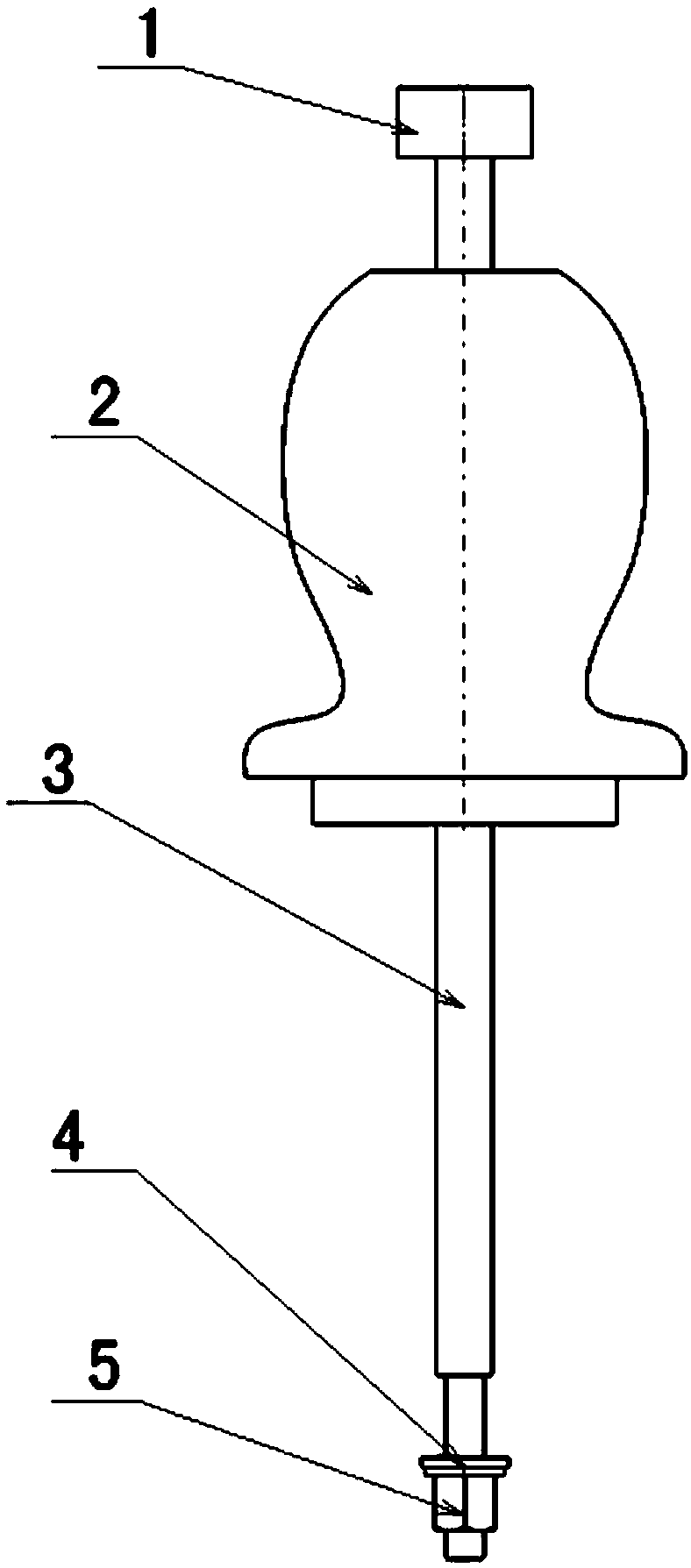
[0012] (1) The handle 2 is assembled on the main body 3, and the end stopper 1 is fixed on the end of the main body 3;

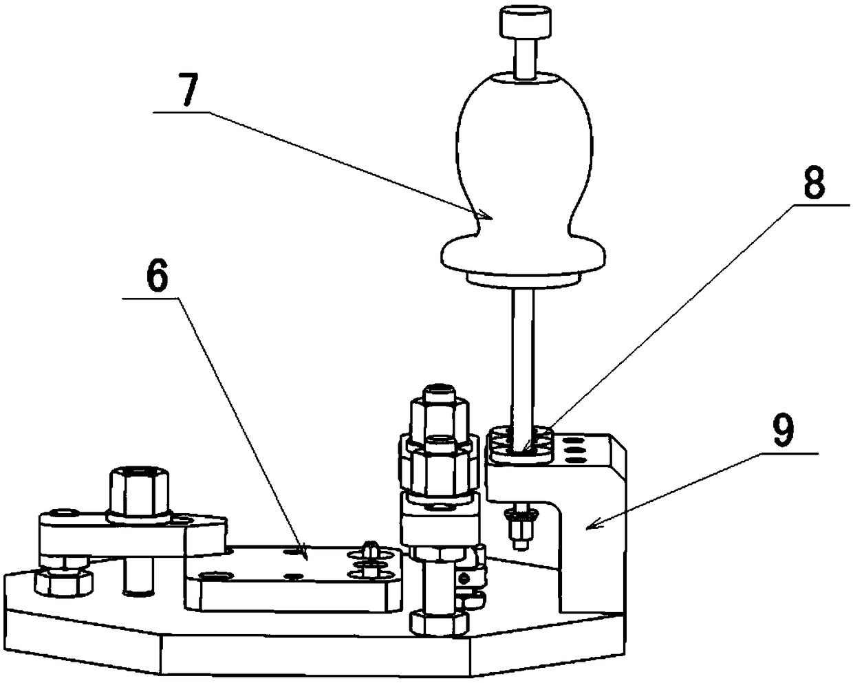
[0013] (2) The part of the lower end of the main body 3 that passes through the center hole of the bushing 8 to be removed is smaller than the inner hole of the bushing. When it is less than 5 mm from the inner hole of the bushing, it is required to add an auxiliary sleeve to realize the gap between the main body 3 and the bushing 8 to be removed;

[0014] (3) The inner hole of the adjusting gasket 4 and the main body 3 adopt clearance fit, and the outer diameter of the adjusting gasket 4 is selected to be 1-2mm smaller than the outer diameter of the bushing 8 to be removed, and the heigh...


PUM


Abstract

The invention provides a disassembly tool used for a shouldered bush of a drilling jig and a use method, and belongs to the technical field of machine disassembly and assembly. The disassembly tool comprises a tip stop piece, a handle, a body, an adjustment gasket and a shouldered nut. The body is of a stepped cylinder structure. By means of an inner hole of the to-be-disassembled bush, it is ensured that the force bearing direction of the to-be-disassembled bush is consistent with the axis direction of the inner hole of the bush. The tip stop piece is arranged on the tip of the body. The handle slides in fixed areas of steps of the body and the tip stop piece. The end tail of the body and the shouldered nut are assembled through a thread and are adjusted through the adjustment gasket. Clearance fit is adopted between the adjustment gasket and the body. By disassembling the shouldered bush through the disassembly tool, replacement of the shouldered bush can be achieved without damaging a bush bottom hole of a drill plate, it is avoided that makeup machining is conducted on the drill plate and the shouldered bush, the shouldered bush is directly replaced with a corresponding standard piece, and the replacement efficiency of the shouldered bush is greatly improved.

Description

technical field [0001] The invention belongs to the technical field of mechanical disassembly and assembly, and in particular relates to a dismantling tool and a use method for a shoulder bush assembled by interference fit on a drilling mold. Background technique [0002] The bushing used to process the hole of the part on the drilling jig will wear out after long-term use, resulting in an out-of-tolerance hole diameter, so that the drilling jig cannot meet the production demand. Therefore, it is often necessary to replace the worn bush. Since the relative distance between the drill template and the main body is relatively close, the operable space during the removal process is small. For the shoulderless bush, it can be used from the side with a large operating space through a small cylindrical pin. The bushing is removed by hammering, and the bushing with a shoulder must be removed from the side without the shoulder, and the maneuverable space in this direction is very sma...

Claims


Application Information

Patent Timeline
Patent Type & Authority Patents(China)
IPC IPC(8): B25B27/02B23B47/28
CPCB23B47/28B25B27/02
Inventor 宗爱国赵金富王鹏张丙营
Owner SHENYANG AIRCRAFT CORP
Why Eureka
Try Eureka