Verification device for in-pile refueling system in liquid-state heavy metal reactor

A liquid heavy metal and verification device technology, which is applied in the direction of reactor fuel elements, reactors, and greenhouse gas reduction, can solve the problems of no verification device, no refueling positioning system component fixed structure verification, etc., to achieve wide applicability, structure Simple, easy-to-use effect

Active Publication Date: 2015-01-07
HEFEI INSTITUTES OF PHYSICAL SCIENCE - CHINESE ACAD OF SCI
View PDF7 Cites 20 Cited by
  • Summary
  • Abstract
  • Description
  • Claims
  • Application Information

AI Technical Summary

Problems solved by technology

[0004] At present, the relevant verification devices of reactor refueling systems at home and abroad have been investigated. In China, only the China Experimental Fast Reactor has built a bench for the key equipment of refueling in the reactor, but the fast reactor verification device is only for two of the key refueling systems in the reactor. The relevant performance of the equipment itself is inspected, but there is no verification of the refueling positioning system, the fixed structure of the components, and the verification of the entire cycle refueling process. There is no relevant verification device in foreign countries.
In addition, there is no

Method used


Image

  • Verification device for in-pile refueling system in liquid-state heavy metal reactor
  • Verification device for in-pile refueling system in liquid-state heavy metal reactor
  • Verification device for in-pile refueling system in liquid-state heavy metal reactor

Examples


Embodiment 1

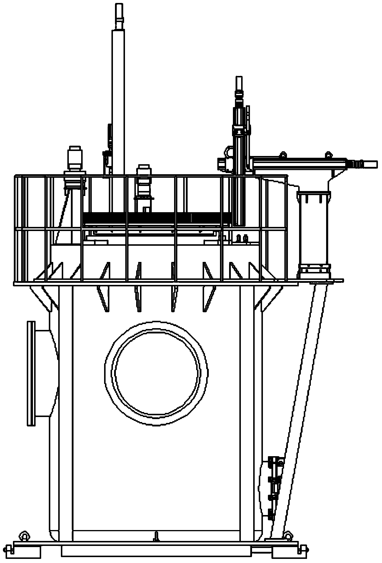
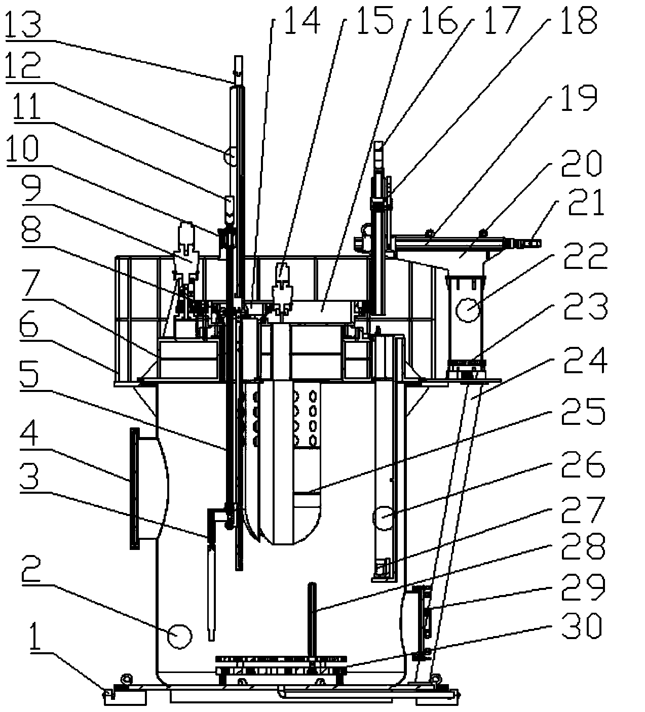
[0025] Such as Figure 1~3 As shown, this embodiment illustrates a verification device for the refueling system in a liquid heavy metal reactor, which mainly consists of a container tank 2, a stack top cover 7, a cock and a driving mechanism 8, a refueling machine 12, an external translation mechanism 22, The elevator 26, the simulated fuel assembly 28 and the grid plate 30 are composed.

[0026] The cock and the driving mechanism 8 are concentrically installed and supported on the stack top cover 7, and are mainly composed of a large cock 16, a large cock drive motor 9, a small cock 14, a small cock drive motor 15 and a central measuring column 25, and the small cock 14 is eccentrically installed on the large cock. Cock 16 on.

[0027] The refueling machine 12 is eccentrically and fixedly installed on the small cock 14, and is mainly composed of the refueling machine spindle 5, the refueling machine grip 3, the refueling machine rotating motor 10, the refueling machine gripp...

Embodiment 2

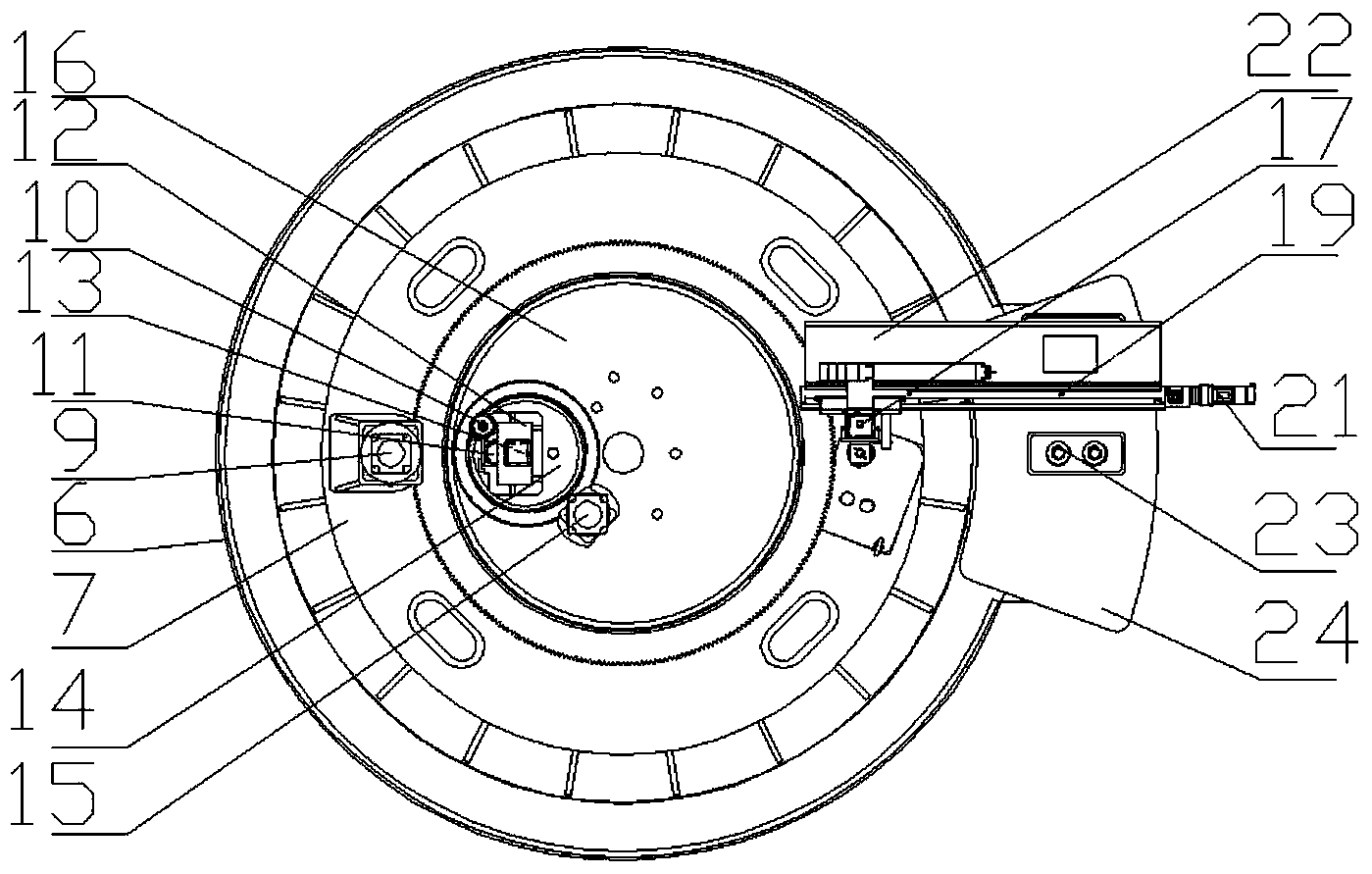
[0033] Such as Figure 4~6 As shown, this embodiment describes in detail the work flow steps of a verification device for a liquid heavy metal reactor refueling system.

[0034] Positioning step: After selecting the analog components that need to be replaced, the large cock drive motor 9 drives the large cock 16 to rotate, the small cock drive motor 15 drives the small cock 14 to rotate, and the refueling machine rotating motor 10 drives the refueling machine gripper 3 turns With the rotation of the main shaft 5 of the refueling machine, through the combined movement of the large and small cocks and the refueling machine, the gripper 3 of the refueling machine is positioned directly above the target simulated fuel assembly 28, and the target simulated fuel assembly 28 is placed on the grid plate 30 On, the elevator rotating slot 27 parked at the upper end of the elevator 26 moves down to the lower end;

[0035] Grabbing steps: the lifting motor 13 of the refueling machine drive...


PUM


Abstract

The invention discloses a verification device for an in-pile refueling system in a liquid-state heavy metal reactor. The device mainly comprises a container tank, a reactor top cover, a cock and a drive mechanism, a refueling machine, an out-of-pile translation mechanism, a lifting machine, a simulated fuel assembly and a grid plate. The cock and the drive mechanism are concentrically arranged and supported on the reactor top cover, and mainly comprise a large cock, a large cock drive motor, a small cock, a small cock drive motor and a center measurement column; the small cock is eccentrically arranged on the large cock. The device is capable of simulating a refueling function of the refueling system in the liquid-state heavy metal reactor under a cold-state air environment, realizing replacement of a reactor core fuel assembly, and providing a verifying platform for design and parameter correction of the refueling system in the ADS liquid-state heavy metal reactor. The device is good in running performance, and verifies the feasibility of the refueling system in a double-cock split type central measurement cylinder reactor.

Description

technical field [0001] The invention belongs to the technical field of refueling of an accelerator-driven subcritical nuclear reactor (ADS reactor for short), and in particular relates to a verification device for an internal refueling system of a lead-bismuth cooled nuclear reactor. Background technique [0002] Accelerator Driven subcritical system (Accelerator Driven subcritical System, ADS) is composed of proton accelerator, liquid heavy metal spallation target and transmutation nuclear waste subcritical reactor. It is a new type of nuclear waste transmutation, nuclear fuel proliferation and energy generation system. Its basic The principle is to use the protons produced by the accelerator to bombard the heavy metal spallation target to generate spallation neutrons, which drive the nuclear fuel in the reactor to undergo a nuclear reaction, and realize the functions of transmutation treatment of nuclear waste, multiplication of nuclear fuel, and energy production. During ...

Claims


Application Information

Patent Timeline
IPC IPC(8): G21C19/02
CPCG21C19/02Y02E30/30
Inventor 曾梅花宋勇高理富丁晓磊吴宜灿
Owner HEFEI INSTITUTES OF PHYSICAL SCIENCE - CHINESE ACAD OF SCI
Why Eureka
Try Eureka