Method for manufacturing line sections of hydraulic lines

A line and section technology, applied in the field of hydraulic blocks, can solve problems such as cost-intensive, cumbersome technology, and time-intensive

Active Publication Date: 2021-07-06
ROBERT BOSCH GMBH
View PDF7 Cites 0 Cited by
  • Summary
  • Abstract
  • Description
  • Claims
  • Application Information

AI Technical Summary

Problems solved by technology

Such production of hydraulic blocks or housing components with line sections of hydraulic lines is technically complex and thus also time-intensive and cost-intensive

Method used


Image

  • Method for manufacturing line sections of hydraulic lines
  • Method for manufacturing line sections of hydraulic lines
  • Method for manufacturing line sections of hydraulic lines

Examples


Embodiment Construction

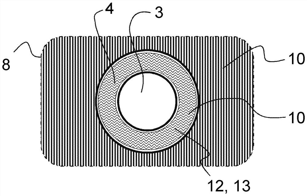
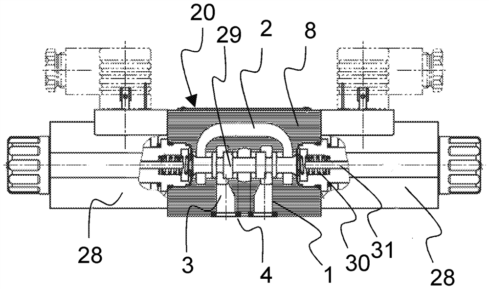
[0044] figure 1 For example, magnetically actuatable directional slide valves are shown for several further components, which can have line sections of the hydraulic line. This directional slide valve is implemented with a housing 20 formed from a solid body 8 manufactured according to the method proposed here. In said housing 20 a (possibly branched) hydraulic line 2 is formed. The hydraulic lines 2 indicated here emerge from the solid body 8 at two points of the housing 20 . There, a line section 1 is formed in each case, which has a channel 3 and a delimited sealing surface 4 surrounding said channel 3 and a space.

[0045] For the sake of illustration, the mode of operation of this magnetically actuatable directional slide valve should be briefly indicated. Two magnets 28 are arranged laterally to the housing 20 , by means of which a control slide 29 arranged in the middle of the housing 20 can be moved. The control slide 29 is moved on both sides by a tappet 31 displa...


PUM


Abstract

A method is proposed for producing a line section (1) of a hydraulic line (2), wherein at least one channel (3) and a spatially limited sealing surface (4) surrounding the channel (3) are produced ). The method is characterized by at least the following steps: (a) providing a layer (5) of loose material (6) on a foundation (7), (b) subjecting the layer ( 5) connected as a solid (8), the ray follows a predetermined path (10) along said layer (5), (c) repeating steps (a) and (b), (d) wherein, so The path (10) is selected in the region of the sealing surface (4) such that it does not touch the boundary (11) of the sealing surface (4).

Description

technical field [0001] The invention relates to a method for producing a line section of a hydraulic line having a channel and a spatially limited sealing surface formed around the channel. The invention finds particular application in hydraulic blocks which are used for conveying fluids, in particular oil, under high pressure. Background technique [0002] The invention is used in particular in valve housing blocks or valves. The valves are usually screwed to the control block and are connected at the connection surface to hydraulic lines formed in the control block. Then, the fluid passage nozzle is connected to the coupling face of the valve. The mouth is surrounded by an annular groove, into which an elastic sealing ring (in particular for axial sealing) is inserted. The sealing ring is formed, for example, from an elastomer and / or is shaped according to the O-ring type with a predetermined inner diameter and a so-called wire diameter. For the use cases described her...

Claims


Application Information

Patent Timeline
Patent Type & Authority Patents(China)
IPC IPC(8): B22F3/105B33Y10/00B33Y80/00
CPCB33Y10/00B33Y80/00B22F10/00B22F10/28B22F5/10C22C33/0285Y02P10/25
Inventor S.布勒德纳A.京德J.L.比罗德
Owner ROBERT BOSCH GMBH
Why Eureka
Try Eureka