A kind of environmental protection dust removal equipment

A dust removal equipment and environmental protection technology, applied in the connection/disconnection of connection devices, contact parts, electrical components, etc., can solve the problems of electric shock, easy loosening and poor contact of users, and achieve the effect of preventing electric shock accidents and facilitating electrical connection.

Active Publication Date: 2018-03-13
阿尔法(江苏)重工科技有限公司
View PDF4 Cites 0 Cited by
  • Summary
  • Abstract
  • Description
  • Claims
  • Application Information

AI Technical Summary

Problems solved by technology

[0002] With the continuous growth of technologies such as industry, medical technology, and food processing, a large amount of dust and exhaust gas will be generated in the manufacturing process of people. Nowadays, people have gradually strengthened their awareness of air quality improvement. In the manufacturing process, usually use The dust collector cleans the dust and exhaust gas. The dust collector needs to be energized through the plug on the wire during use. However, in the existing technology, the ordinary dust collector plug is prone to arcing due to the influence of voltage during the plugging and unplugging process. It is easy to cause electric shock to the user, which has a certain potential danger to the user, and there is poor plug stability, easy to loosen, resulting in poor contact, and because there is a large current flowing through the socket, the plug of the dust collector is easily damaged

Method used


Image

  • A kind of environmental protection dust removal equipment
  • A kind of environmental protection dust removal equipment
  • A kind of environmental protection dust removal equipment

Examples


Embodiment Construction

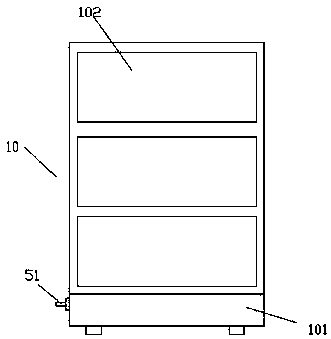
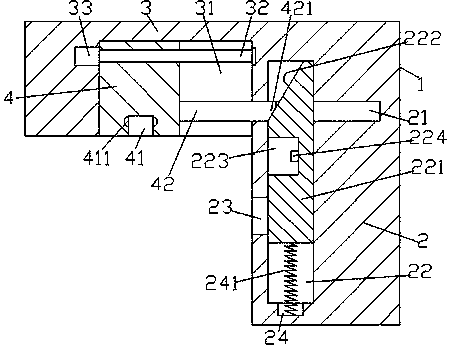
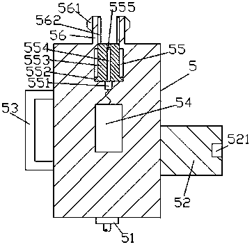
[0021] Such as Figure 1-Figure 6 As shown, a kind of environment-friendly dust removal equipment of the present invention includes a dust collector 10 and an electrification device. The front end of the dust collector 10 is provided with a plurality of door panels 102, and the bottom of the dust collector 10 is provided with a dust collection drawer 101. The electrification The device includes an electrified foundation pile 1 and an electrical device 5 composed of a pin end 3 and an electrified end 2. The pin end 3 is fixedly arranged at the upper left side of the electrified end 2. Sliding groove 31, the first helical rod 32 extending left and right is arranged in the described sliding groove 31, the left end of the first helical rod 32 is connected with the first driving machine 33, and the first helical rod The right end of 32 is rotationally connected with the inner end of the right side of the sliding groove 31, and the first helical rod 32 is provided with a helically f...


PUM


Abstract

The invention discloses environment protection dust removing equipment. The environment protection dust removing equipment comprises a dust remover and an electrifying apparatus, wherein a plurality of door plates are arranged on the front end part of the dust remover; a dust collecting drawer is arranged at the bottom of the dust remover; the electrifying apparatus comprises an electrifying base pile which consists of a bolt end and an electrifying end, and an electrifying appliance; the bolt end is fixedly arranged in a position on the upward side of the left side of the electrifying end; a shift-in sliding groove is formed in the end plane at the bottom of the bolt end; a first spiral rod which is arranged in an extension manner left and right is arranged in the shift-in sliding groove; the left side end of the first spiral rod is connected with a first driver; the right side end of the first spiral rod is connected with the inner end of the right side of the shift-in sliding groove in a rotary and matching manner; the first spiral rod is provided with a clamping shifting-in block which is connected in a spiral matching manner; and a shifting-in shaft which is arranged in an extension manner towards the right side is arranged on the end plane on the right side of the clamping shifting-in block below the first spiral rod. The environment protection dust removing equipment is simple in structure, and capable of realizing automatic electrification plugging, automatically controlling exposure and hiding operations of an electrifying rod, and improving working efficiency and safety.

Description

technical field [0001] The invention relates to the field of dust removal facilities, in particular to environmental protection dust removal equipment. Background technique [0002] With the continuous growth of technologies such as industry, medical technology, and food processing, a large amount of dust, exhaust gas, etc. will be generated in the manufacturing process of people. Nowadays, people have gradually strengthened their awareness of air quality improvement. In the manufacturing process, usually use The dust collector cleans the dust and exhaust gas. The dust collector needs to be energized through the plug on the wire during use. However, in the existing technology, the ordinary dust collector plug is prone to arcing due to the influence of voltage during the plugging and unplugging process. It is easy to cause electric shock to the user, which has certain potential danger to the user, and there is poor plug stability, easy to loosen, resulting in poor contact, an...

Claims


Application Information

Patent Timeline
Patent Type & Authority Patents(China)
IPC IPC(8): H01R43/26H01R13/24H01R13/629H01R13/64
CPCH01R13/24H01R13/629H01R13/641H01R43/26
Inventor 姚国强
Owner 阿尔法(江苏)重工科技有限公司
Why Eureka
Try Eureka