
Light guide plate, backlight module group and display device

A technology of backlight module and light guide plate, applied in the direction of light guide, optics, optical components, etc., can solve the problems of display panel interference fringes or rainbow patterns, large dot diameter, visible dots and interference fringes, etc.

Active Publication Date: 2017-07-11
SHENZHEN TCL NEW-TECH CO LTD
View PDF9 Cites 2 Cited by
  • Summary
  • Abstract
  • Description
  • Claims
  • Application Information

AI Technical Summary

Problems solved by technology

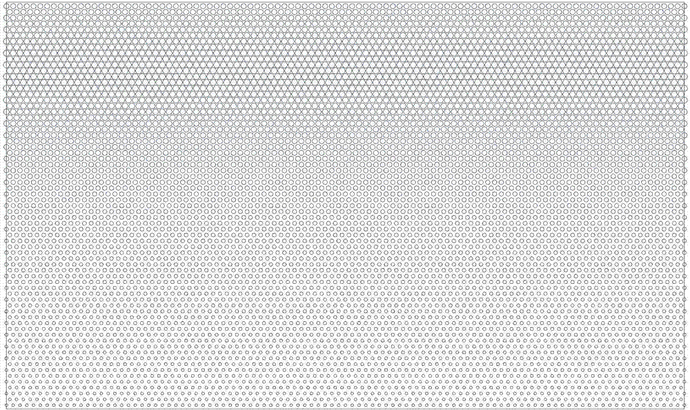
[0003] But existing light guide plate is more regular because of dot arrangement design, and the diameter of dot increases gradually from near light end to far light end (referring to figure 1 ), resulting in an excessively large dot diameter at the far light end on the light guide plate
The light from the light source enters the light guide plate from the near light end. Because the dots on the light guide plate are arranged regularly, when the light is reflected and refracted by the regularly arranged dots to the light-emitting surface, a uniform surface light source cannot be formed, and interference fringes or rainbow patterns will easily appear on the display panel.
At the same time, the multiple reflections and refractions of the light by the dots at the near light end make only part of the light transmitted to the far light end, resulting in the weakening of the light at the far light end. When the light is reflected by the dots and refracted to the light-emitting surface again, it is almost impossible to form a surface light source, making the display panel visible dots, interference fringes or rainbow patterns.
[0004] Furthermore, the optical film in the existing backlight module usually adopts the traditional four, three or two films to form the optical film group, which makes the optical film group very thick and expensive; at the same time, the traditional laser 1. The dots of the light guide plate are made by the printing process, resulting in a larger diameter of the dots (the diameter range of the dots made by laser: 100 μm to 300 μm, the diameter range of the dots made by printing: 250 μm to 1000 μm), which also leads to the difference between the film structure and Technical problems such as dot visibility and interference fringes are prone to appear between display panels

Method used


Image

  • Light guide plate, backlight module group and display device
  • Light guide plate, backlight module group and display device
  • Light guide plate, backlight module group and display device

Examples


Embodiment Construction

[0026] The technical solutions in the embodiments of the present invention will be clearly and completely described below in conjunction with the accompanying drawings in the embodiments of the present invention. Obviously, the described embodiments are only a part of the embodiments of the present invention, rather than all the embodiments. Based on the embodiments of the present invention, all other embodiments obtained by those of ordinary skill in the art without creative work shall fall within the protection scope of the present invention.

[0027] It should be noted that all the directional indications (such as up, down, left, right, front, back...) in the embodiments of the present invention are only used to explain the difference between components in a specific posture (as shown in the accompanying drawings). If the relative positional relationship, movement situation, etc. change, the directional indication will change accordingly.

[0028] In the present invention, unles...


PUM

PropertyMeasurementUnit
Diameteraaaaaaaaaa
Thicknessaaaaaaaaaa
Thicknessaaaaaaaaaa

Abstract

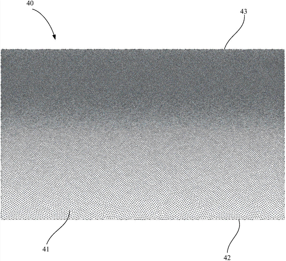
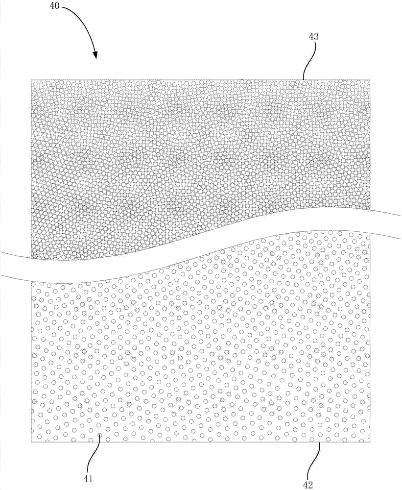
The invention discloses a light guide plate, a backlight module group and a display device. The light guide plate comprises a near light end and a far light end, a number of screen dots are arranged on the light guide plate in a spaced manner, the screen dots are same in diameter, and distance between neighboring screen dots gradually decreases from the near light end to the far light end. The display device employing the light guide plate can be prevented from phenomena of visible screen dots, interference fringes and the like.

Description

Technical field [0001] The invention relates to the field of liquid crystal television display technology, and in particular to a light guide plate, a backlight module using the light guide plate, and a display device using the backlight module. Background technique [0002] At present, as a display component of electronic equipment, liquid crystal display devices have been widely used in various electronic products, and the backlight module is an important component of the liquid crystal display device. The backlight modules are divided into two types: side-type backlight modules and direct-type backlight modules according to the different incident positions of the light source. The direct type backlight module is a light source such as CCFL (Cold Cathode Fluorescent Lamp, cathode fluorescent lamp) or LED (Light Emitting Diode light-emitting diode) installed behind the display panel, the linear light source is converted into a surface light source to provide Display panel. The...

Claims


Application Information

Patent Timeline
IPC IPC(8): G02B6/00
CPCG02B6/0036G02B6/0058
Inventor 邓天应潘俊强科文季红雷李健林许怀书
Owner SHENZHEN TCL NEW-TECH CO LTD
Learn More