Supercharge Your Innovation With Domain-Expert AI Agents!

An adjustable plate punching device capable of automatically controlling clamping

A punching device and adjustable technology, applied in the field of sheet metal processing, can solve the problems of reduced production efficiency, unfavorable production, poor stabilization effect, etc., and achieve the effects of high accuracy and precision, improved production efficiency, and high stabilization effect.

Active Publication Date: 2018-07-27
NANTONG KEDA BUILDING MATERIALS +1
View PDF8 Cites 0 Cited by
  • Summary
  • Abstract
  • Description
  • Claims
  • Application Information

AI Technical Summary

Problems solved by technology

[0002] In the modern industrial production process, in order to improve the stability of the plate processing and prevent the plate from shifting during the plate punching process, the plate is often clamped by a clamp. The traditional punching and fixing mechanism needs to be manually fixed, which is time-consuming and laborious. The stability effect is poor, and deviations are easy to occur. The accuracy and precision of drilling cannot be well guaranteed, resulting in low production efficiency and low pass rate of workpiece products, which greatly reduces production efficiency and is not conducive to production.

Method used


Image

  • An adjustable plate punching device capable of automatically controlling clamping
  • An adjustable plate punching device capable of automatically controlling clamping
  • An adjustable plate punching device capable of automatically controlling clamping

Examples


Embodiment Construction

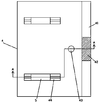
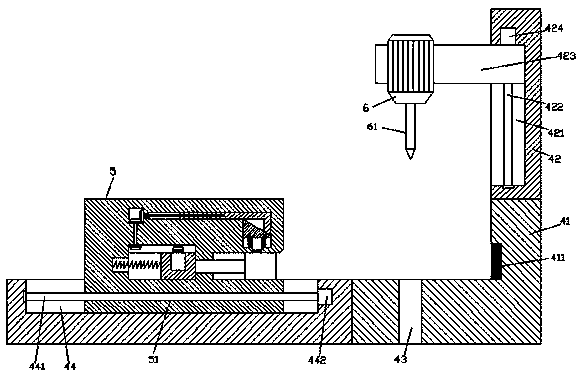
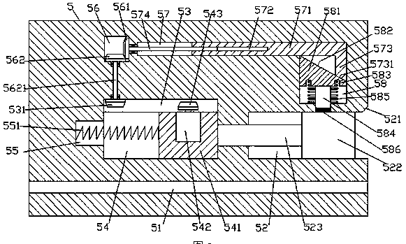
[0028] Such as Figure 1-Figure 9 As shown, an adjustable plate punching device that can automatically control clamping of the present invention includes a body 4, and first sliding grooves 44 are symmetrically provided in the front and rear top end surfaces of the body 4, and each of the first sliding The slot 44 is slidingly fitted with a clamping mechanism 5 whose top protrudes from the top end surface of the body 4. The clamping mechanism 5 in the first sliding slot 44 is provided with a first threaded hole 51 extending left and right. , the clamping mechanism 5 above the first threaded hole 51 is provided with a first sliding cavity 54, and the top of the first sliding cavity 54 is connected with a first transmission cavity 53, and the first sliding cavity 54 A sliding block 541 is slidably connected inside, and a clamping sliding groove 52 is provided in the right side end surface of the clamping mechanism 5 on the right side of the first sliding cavity 54, and a pushing...


PUM


Abstract

The invention discloses an adjustable plate perforating device capable of automatically controlling clamping. The adjustable plate perforating device comprises a machine body. First sliding grooves are symmetrically formed in the end faces of the front top and the rear top of the machine body. A clamping mechanism with the top stretching out of the end face of the top of the machine body is connected in each first sliding groove in a sliding fit manner. A first threaded hole extending left and right is formed in the clamping mechanism in each first sliding groove. A first sliding cavity is formed in the position, above the corresponding first threaded hole, in each clamping mechanism. A first transmission cavity is formed in the top of each first sliding cavity in a communicating manner. A sliding block is connected in each first sliding cavity in a sliding manner. A clamping sliding groove is formed in the position, on the right side of the corresponding first sliding cavity, of the end face of the right side of each clamping mechanism. A pushing block is connected in each clamping sliding groove in a sliding manner. A locking motor is fixedly arranged in the end face of the top of each sliding block. A first conic wheel stretching into the corresponding first transmission cavity is connected to the top of each locking motor in a matched manner. A second transmission cavity is formed in the position, above the left side of the corresponding first transmission cavity, in each clamping mechanism. The adjustable plate perforating device is simple in structure, time and labor are saved, deviation is not prone to being generated, and production efficiency is improved.

Description

technical field [0001] The invention relates to the technical field of plate processing, in particular to an adjustable plate punching device capable of automatically controlling clamping. Background technique [0002] In the modern industrial production process, in order to improve the stability of the plate processing and prevent the plate from shifting during the plate punching process, the plate is often clamped by a clamp. The traditional punching and fixing mechanism needs to be manually fixed, which is time-consuming and laborious. The stabilization effect is poor, deviations are easy to occur, and the accuracy and precision of drilling cannot be well guaranteed, resulting in low production efficiency and low pass rate of workpiece products, which greatly reduces production efficiency and is not conducive to production. Contents of the invention [0003] The technical problem to be solved by the present invention is to provide an adjustable plate punching device cap...

Claims


Application Information

Patent Timeline
Patent Type & Authority Patents(China)
IPC IPC(8): B27C3/00
CPCB27C3/00
Inventor 钱忠勤朱赋朱胤储开平陈春林
Owner NANTONG KEDA BUILDING MATERIALS
Features
  • R&D
  • Intellectual Property
  • Life Sciences
  • Materials
  • Tech Scout
  • Unparalleled Data Quality
  • Higher Quality Content
  • 60% Fewer Hallucinations
Learn More